Rotating/non-rotating tibia base plate/insert system

a tibia base plate and non-rotating technology, applied in the field of orthopaedic prostheses, can solve the problems of knee joint failure under some loading conditions, knee articulation surface deformation, unstable knee,

Active Publication Date: 2012-01-31
ZIMMER INC
View PDF42 Cites 12 Cited by
  • Summary
  • Abstract
  • Description
  • Claims
  • Application Information

AI Technical Summary

Benefits of technology

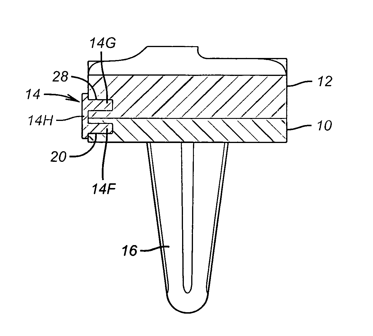
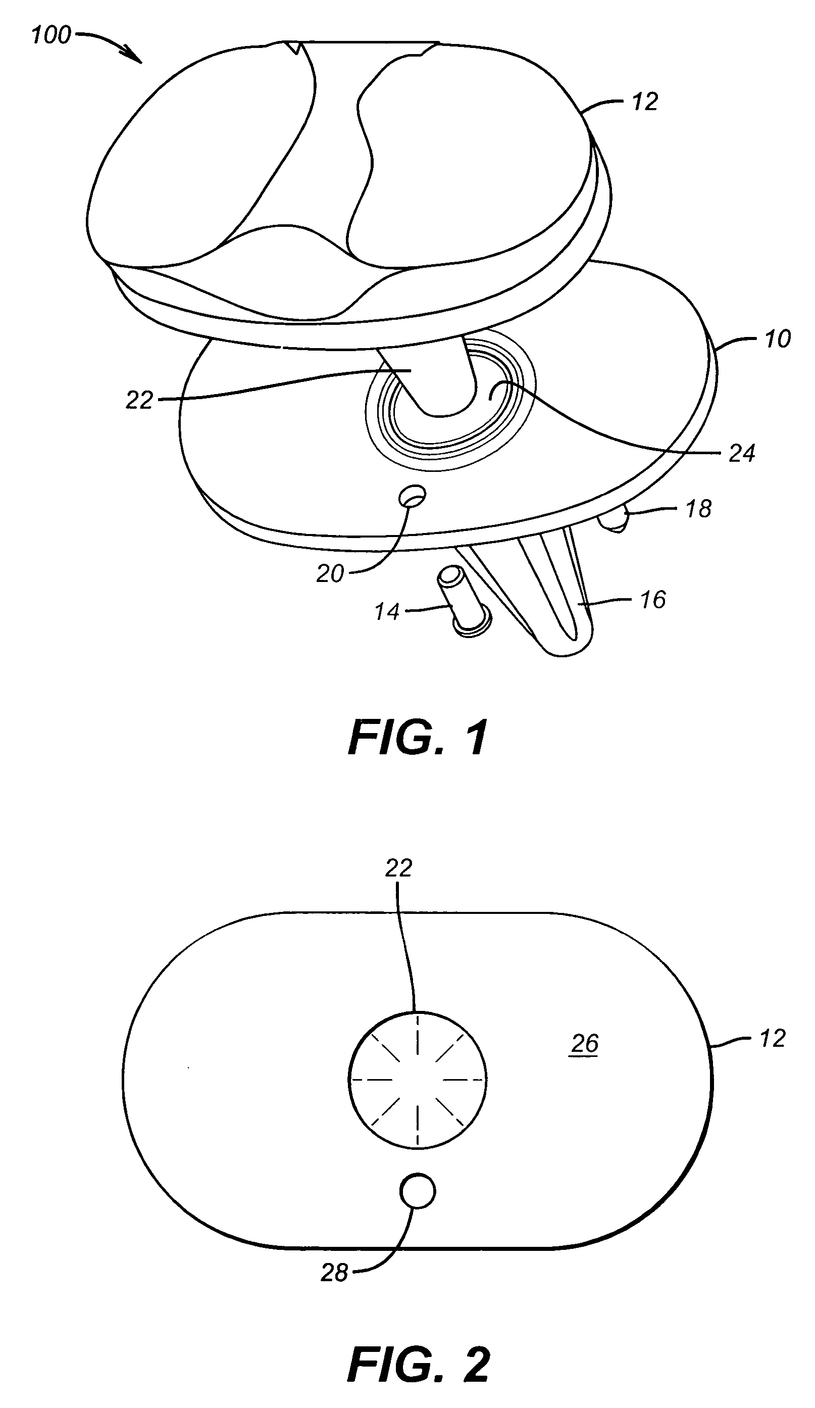
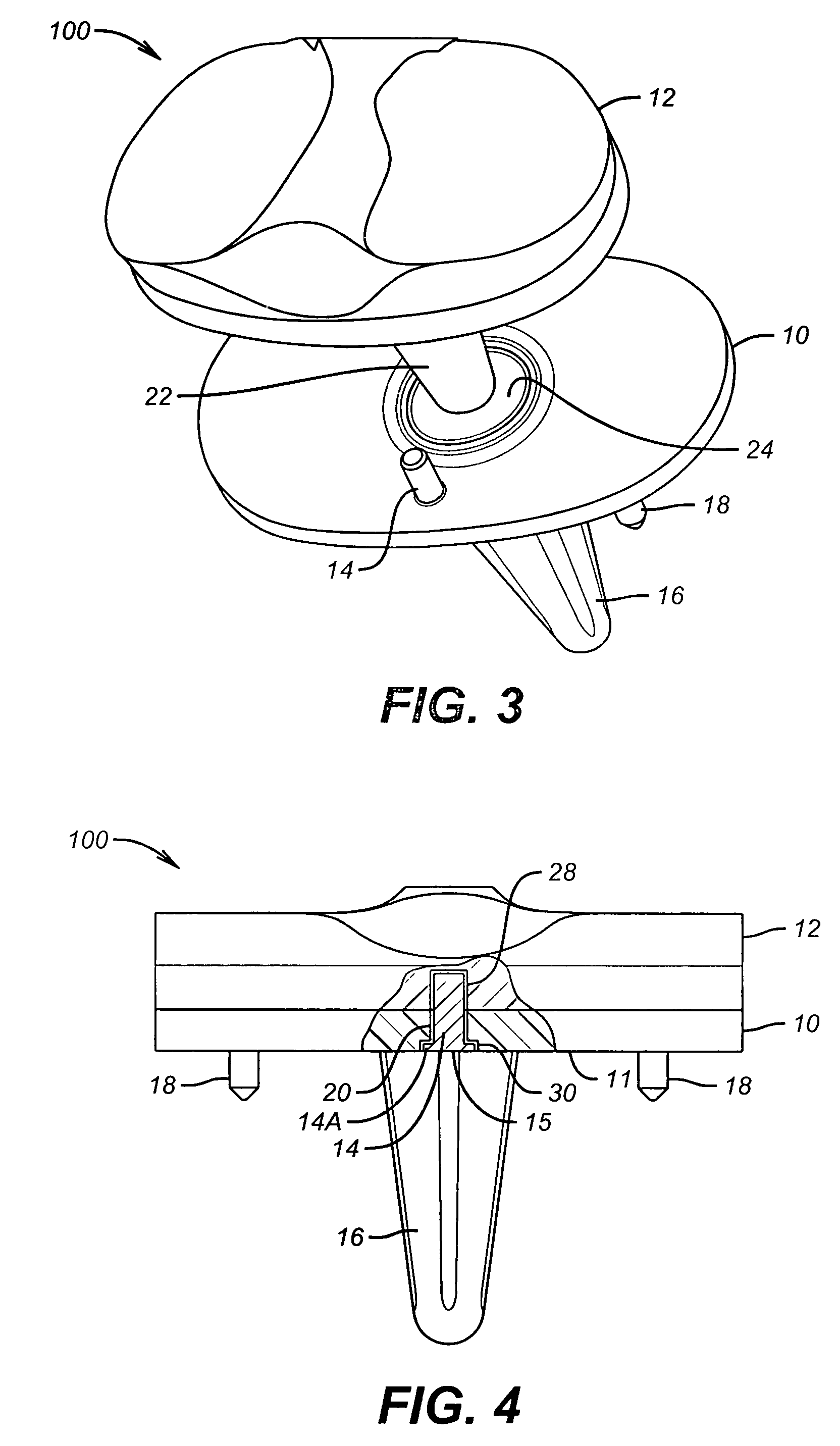
[0010]The present invention is directed to a rotating / non-rotating tibia base plate / insert system. In one illustrative embodiment, the device comprises a tibia base plate, an insert adapted to be positioned above the base plate, and at least one removable pin that, when installed, engages at least a portion of the insert and the base plate to thereby prevent relative rotation between the insert and the base plate.
[0011]In another illustrative embodiment, the device comprises a tibia base plate having an opening formed therein, an insert adapted to be positioned above the base plate, the insert having an opening formed therein, and at least one removable pin that, when installed, engages the opening in the base plate and the opening in the insert to thereby prevent relative rotation between the insert and the base plate.
[0012]In yet another illustrative embodiment, the device comprises a tibia base plate having an opening formed therein, an insert adapted to be positioned above the base plate, the insert having an opening formed therein, and at least one removable pin that, when installed, engages the opening in the base plate and the opening in the insert to thereby prevent relative rotation between the insert and the base plate, wherein the pin has a head that is positioned adjacent a bottom surface of the base plate.

Problems solved by technology

Because of aging and disease, the articulating surfaces of the knee may degrade.
For example, if the various ligaments that support the knee are weak or have been previously damaged, allowing rotation of the tibia insert relative to the tibia base plate may create an unstable knee.
In a worst case scenario, allowing such rotation may lead to failure of the knee joint under some loading conditions.
However, the decision to use a rotating or non-rotating insert may not be finally made until some point during the process of the surgery.
Obviously, such situations involved major surgery, which patients might be reluctant to endure.

Method used


Image

  • Rotating/non-rotating tibia base plate/insert system
  • Rotating/non-rotating tibia base plate/insert system
  • Rotating/non-rotating tibia base plate/insert system

Examples


Embodiment Construction

[0034]Illustrative embodiments of the invention are described below. In the interest of clarity, not all features of an actual implementation are described in this specification. It will of course be appreciated that in the development of any such actual embodiment, numerous implementation-specific decisions must be made to achieve the developers' specific goals, such as compliance with medical-related, system-related and business-related constraints, which will vary from one implementation to another. Moreover, it will be appreciated that such a development effort might be complex and time-consuming, but would nevertheless be a routine undertaking for those of ordinary skill in the art having the benefit of this disclosure.

[0035]The present invention will now be described with reference to the attached figures. The words and phrases used herein should be understood and interpreted to have a meaning consistent with the understanding of those words and phrases by those skilled in the...


PUM


Abstract

The present invention is directed to a rotating / non-rotating tibia base plate / insert system. In one illustrative embodiment, the device comprises a tibia base plate, an insert adapted to be positioned above the base plate, and at least one removable pin that, when installed, engages at least a portion of the insert and the base plate to thereby prevent relative rotation between the insert and the base plate. In one illustrative embodiment, the method comprises obtaining a prosthetic knee assembly comprised of a tibia base plate, a tibia insert and a removable pin, the assembly being adapted to be configured in a first state such that the tibia insert may rotate relative to the base plate or in a second state such that said tibia insert cannot rotate relative to said base plate, making at least one incision adjacent a patient's knee, installing the prosthetic knee assembly in the patient, wherein the removable pin is removed such that the assembly is in the first state wherein the tibia insert may rotate relative to the tibia base plate, and closing the incision.

Description

PRIORITY CLAIM[0001]Applicants hereby claim priority based upon U.S. Provisional Patent Application Ser. No. 60 / 444,817, filed Feb. 4, 2003, entitled “Rotating Tibial Baseplate / Insert System,” the entirety of which is hereby incorporated by reference.BACKGROUND OF THE INVENTION[0002]1. Field of the Invention[0003]The present invention is generally related to the field of orthopedic prostheses, and, more particularly, to a rotating / non-rotating tibia base plate / insert system.[0004]2. Description of the Related Art[0005]The two largest and longest bones of the human body, the femur and tibia, meet at a person's knee. The tibia is situated at the front and inner side of the lower leg. The head of the tibia is large and expanded on each side into two eminences, the tuberosities. These eminences form two smooth concave compartments or surfaces which articulate with the condyles of the femur. The medial condyle is more prominent anteriorly and broader both in the anterior-posterior and tr...

Claims


Application Information

Patent Timeline
Patent Type & Authority Patents(United States)
IPC IPC(8): A61F2/38
CPCA61F2/3868
Inventor PERRONE, JR., CHARLES H.HOFMANN, AARON A.BURROWS, JAMES WILLIAM
Owner ZIMMER INC
Why Eureka
Try Eureka