Thin-film bulk acoustic resonators having perforated resonator body supports that enhance quality factor

Active Publication Date: 2012-01-31
INTEGRATED DEVICE TECH INC
View PDF38 Cites 10 Cited by
  • Summary
  • Abstract
  • Description
  • Claims
  • Application Information

AI Technical Summary

Benefits of technology

[0005]Micro-electromechanical acoustic resonators according to some embodiments of the present invention include a substrate having a cavity therein and a resonator body suspended over the cavity. The resonator body is anchored on opposing sides thereof (by support beams) to first and second portions of the substrate. These first and second portions of the substrate, which extend over the cavity as first and second ledges, respectively, each have at least one perforation therein dis

Problems solved by technology

Anchor loss or support damping is one of

Method used


Image

  • Thin-film bulk acoustic resonators having perforated resonator body supports that enhance quality factor
  • Thin-film bulk acoustic resonators having perforated resonator body supports that enhance quality factor
  • Thin-film bulk acoustic resonators having perforated resonator body supports that enhance quality factor

Examples


first embodiment

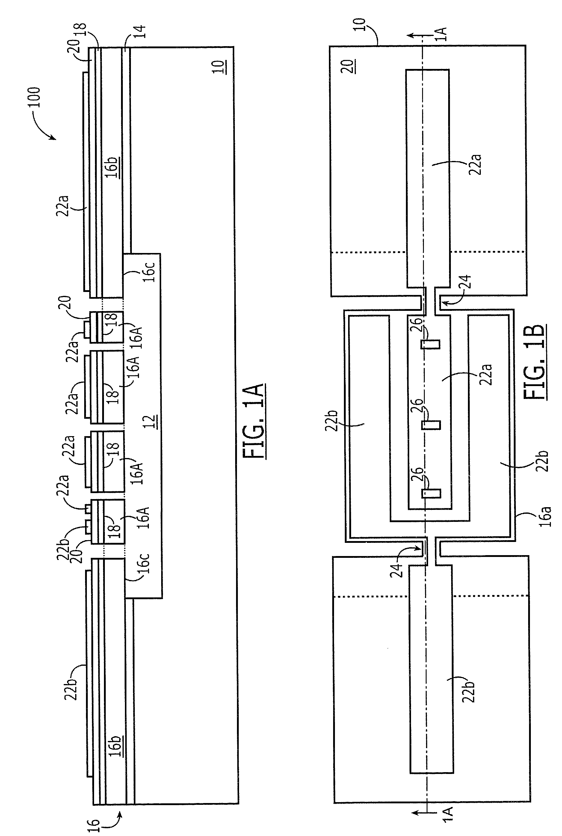
[0029]FIGS. 1A-1B illustrate a micro-electromechanical acoustic resonator 100 according to the present invention. This resonator 100 includes a substrate 10 (e.g., silicon substrate) having a cavity 12 therein. A first electrically insulating layer 14 (e.g., silicon dioxide) is formed on a primary surface of the substrate 10 and a resonator body layer 16 is formed on the first electrically insulating layer 14. The resonator body layer 16 (e.g., silicon layer), first electrically insulating layer 14 and substrate 10 may collectively define a semiconductor-on-insulator (SOI) substrate. A bottom electrode layer 18 (e.g., Mo, Al), a piezoelectric layer 20 (e.g., AlN) and an upper electrode layer (e.g., Mo, Al) are formed on the resonator body layer 16. As illustrated, the upper electrode layer is patterned to define a first electrode 22a and a second electrode 22b. The resonator body layer 16 is also patterned to define a suspended resonator body 16a having a plurality of perforations 2...

second embodiment

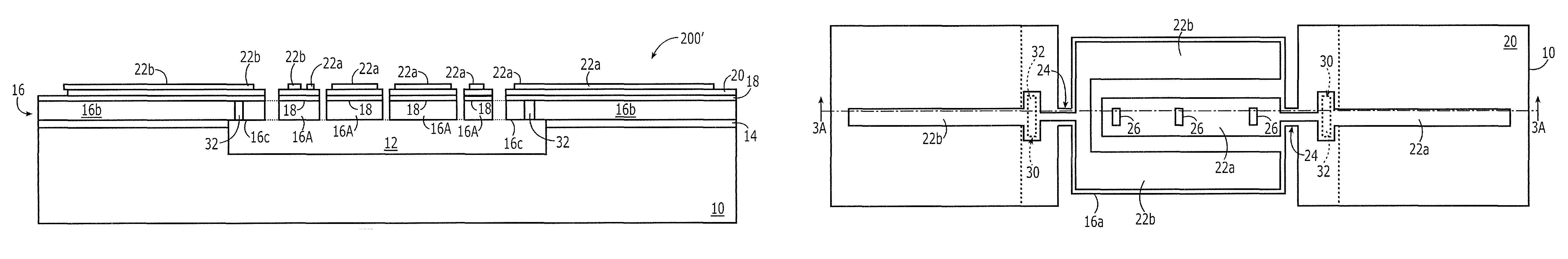
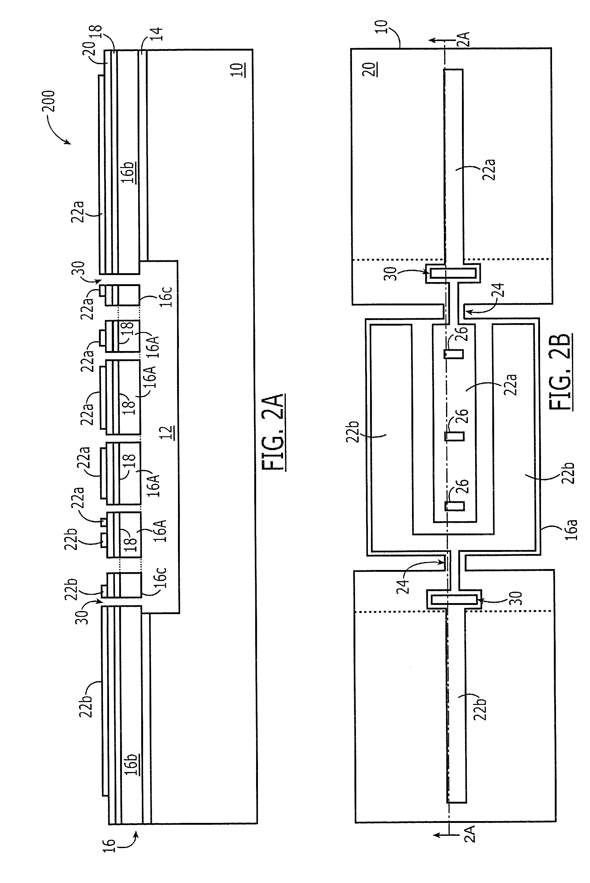
[0030]FIGS. 2A-2B illustrate a micro-electromechanical acoustic resonator 200 according to the present invention. This resonator 200 is similar to the resonator 100 of FIG. 1, however, each of the first and second ledges 16c is further provided with a perforation 30 therein in order to increase the quality (Q) of the resonator 200 by reducing the amount of energy transferred from the suspended resonator body 16a to the surrounding portions 16b of the resonator body layer 16 during each vibration cycle. As illustrated, these perforations 30, which extend closely adjacent respective support beams 24, may have centers that are collinear with the centers of the perforations 26. More preferably, the perforation(s) 26 in the resonator body 16a and the perforations 30 in the first and second ledges 16c are aligned to a nodal line of the resonator body 16a when the resonator body is operating at a resonant frequency. Referring now to FIGS. 3A-3B, the performance of the micro-electromechanic...


PUM


Abstract

Micro-electromechanical acoustic resonators include a substrate having a cavity therein and a resonator body suspended over the cavity. The resonator body is anchored on opposing sides thereof (by support beams) to first and second portions of the substrate. These first and second portions of the substrate, which extend over the cavity as first and second ledges, respectively, each have at least one perforation therein disposed over the cavity. These perforations may be open or filled. The first and second ledges are formed of a first material (e.g., silicon) and the first and second ledges are filled with a second material having a relatively high acoustic impedance relative to the first material. This second material may include a material selected from a group consisting of tungsten (W), copper (Cu), molybdenum (Mo).

Description

CROSS-REFERENCE TO RELATED APPLICATION[0001]This application is related to U.S. application Ser. No. 12 / 393,566, filed Feb. 26, 2009, the disclosure of which is hereby incorporated herein by reference.FIELD OF THE INVENTION[0002]The present invention relates to integrated circuit devices and, more particularly, to micro-electromechanical devices and methods of forming same.BACKGROUND OF THE INVENTION[0003]The quality factor (Q) of a mechanical resonator is defined as the energy stored in the resonator divided by the energy dissipated per vibration cycle. This means the lower the energy loss, the higher the quality factor. Various loss mechanisms will contribute to energy dissipation within a thin-film bulk acoustic resonator, including anchor loss, surface loss, air damping and thermoplastic damping. For a thin-film piezoelectric-on-substrate (TPoS) resonator, the loss mechanisms can be from the surface loss associated with the electrode and the piezoelectric layers, the energy diss...

Claims


Application Information

Patent Timeline
IPC IPC(8): H03H9/00H01L41/08
CPCH03H9/2463H03H2009/02251H03H2009/0244H03H2009/241
Inventor WANG, YELEE, SEUNGBAEBHUGRA, HARMEET
Owner INTEGRATED DEVICE TECH INC
Why Eureka
Try Eureka