
Image pickup apparatus

a pickup apparatus and image technology, applied in the field of image pickup apparatus, can solve the problems of requiring a longer focus detection time period, too shallow depth of field to provide the face area cannot be detected with the pan focus process, so as to shorten the focus control time period

Inactive Publication Date: 2012-01-31
CANON KK
View PDF4 Cites 0 Cited by
  • Summary
  • Abstract
  • Description
  • Claims
  • Application Information

AI Technical Summary

Benefits of technology

The present invention provides an image pickup apparatus that can quickly focus on a subject. It includes a face detector, a focus lens position extractor, a focus control range setting part, and an autofocus controller. The apparatus can detect the position of a person's face and quickly focus on them using the autofocus control. This saves time and makes it easier to capture images.

Problems solved by technology

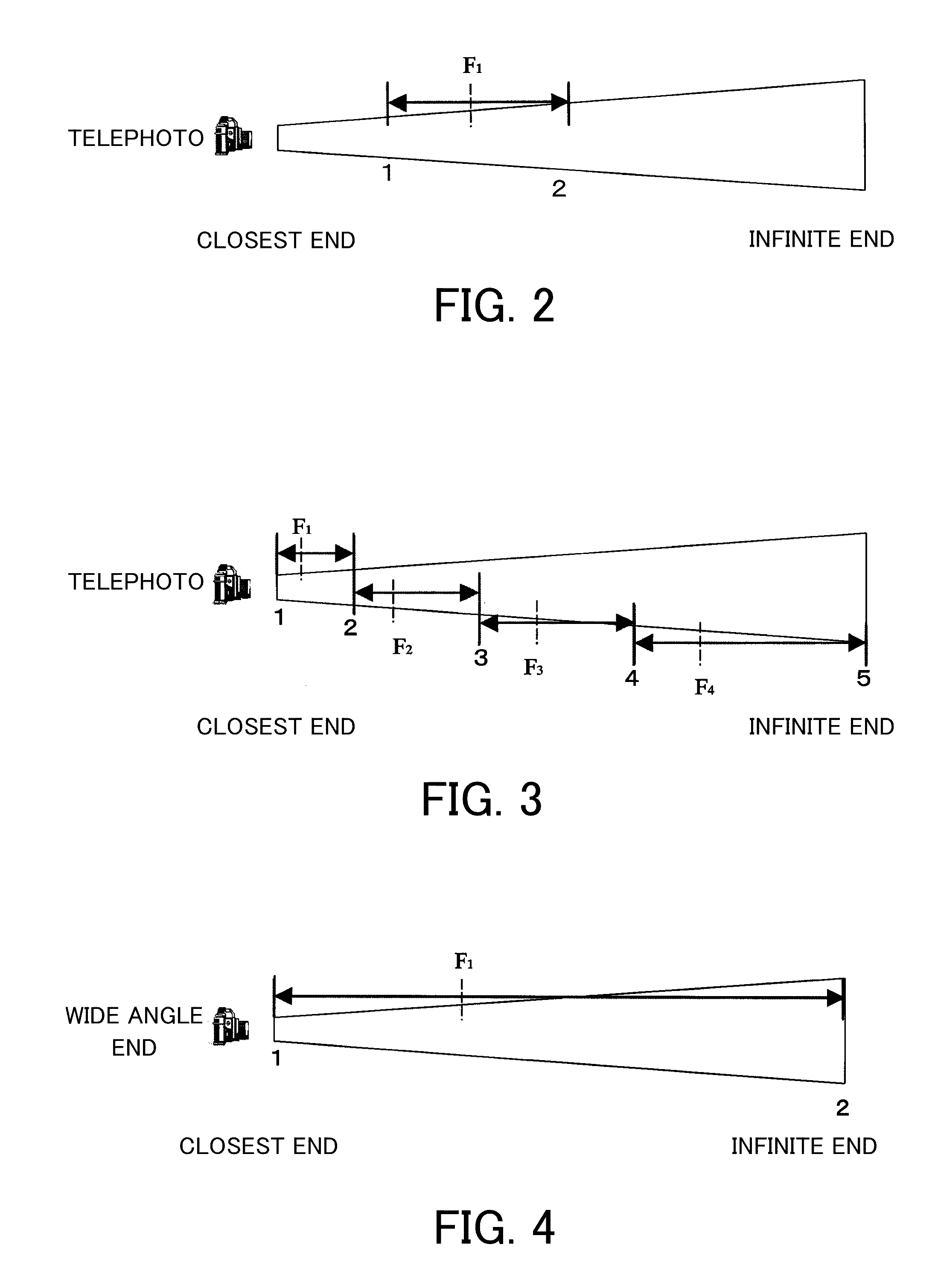
However, according to the contrast type focus detection, an image plane moving amount becomes large from the closest end to the infinite end as a focal length of an imaging lens is longer, requiring a longer focus detection time period.
In addition, as the focal length of the imaging lens is longer, a depth of field becomes too shallow to provide the pan focus process and the face area cannot be detected with the pan focus process.

Method used


Image

  • Image pickup apparatus
  • Image pickup apparatus
  • Image pickup apparatus

Examples


first embodiment

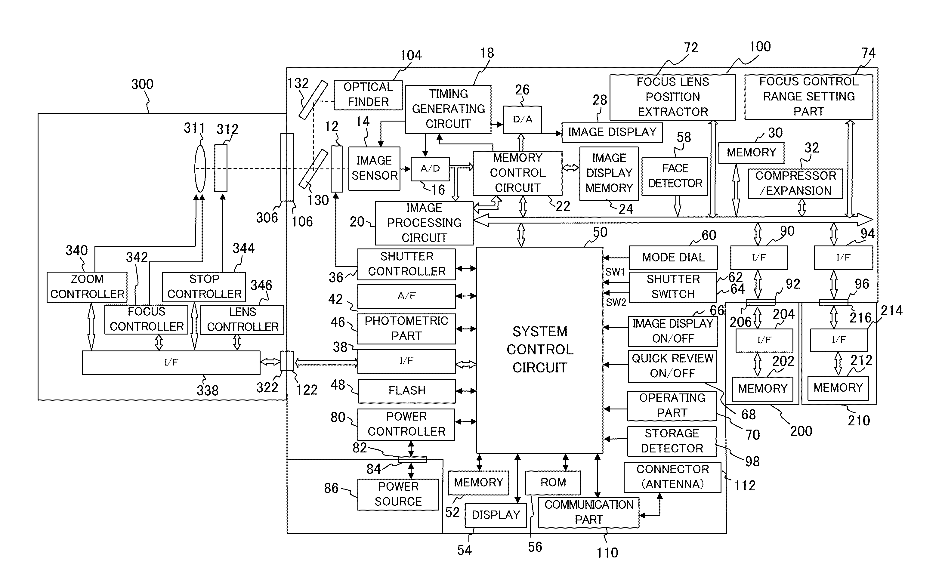
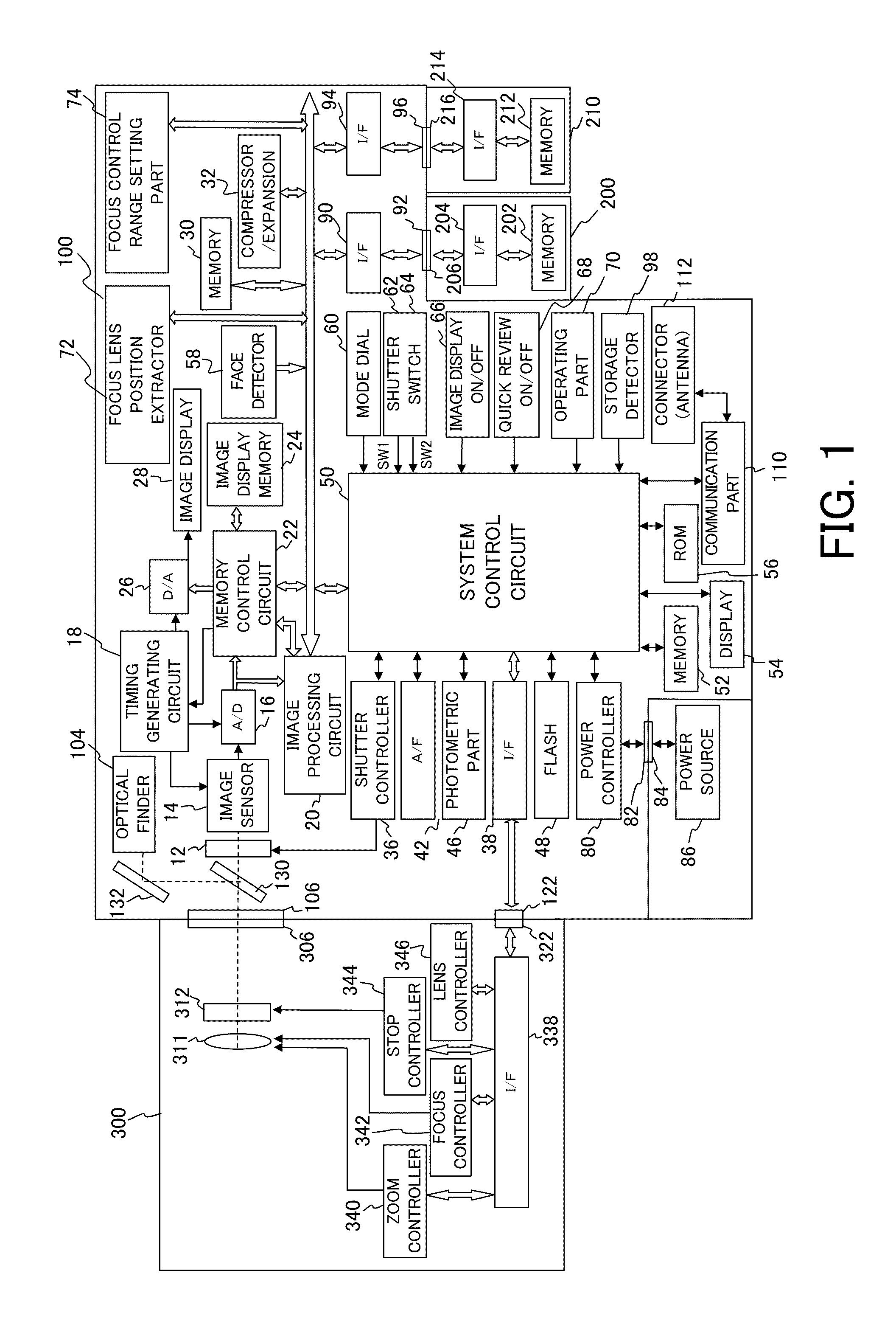
[0029]FIG. 1 is a block diagram of a lens exchange type digital camera according to a first embodiment. The digital camera shown in FIG. 1 includes a camera body (image pickup apparatus) 100, and a lens unit (image pickup optical system) 300 that can be exchangeably attached to the camera body 100.

[0030]Reference numeral 12 denotes a shutter configured to control an exposure amount to an image sensor 14. Reference numeral 14 denotes the image sensor configured to convert an optical image into an electric signal. Reference numeral 16 denotes an A / D converter configured to convert an analog signal into a digital signal (image data). Reference numeral 18 denotes a timing generating circuit configured to supply a clock signal and a control signal to the image sensor 14, the A / D converter 16, and a D / A converter 26, and is controlled by a memory control circuit 22 and a system control circuit 50.

[0031]Reference numeral 20 denotes the image processing circuit configured to provide a pixel...

second embodiment

[0108]FIG. 17 is a block diagram of a lens united type digital camera according to a second embodiment. Those elements in FIG. 17, which are the corresponding elements in FIG. 1, are designated by the same reference numerals, and a description thereof will be omitted.

[0109]Reference numeral 411 denotes an imaging lens, which includes a focus lens and a zoom lens. Reference numeral 412 denotes a shutter having a stop function. Reference numeral 440 denotes an exposure controller that controls the shutter 412 having the stop function, and has a flash compensation function in association with the flash 48. Reference numeral 442 denotes a focus detection controller configured to control focusing of the imaging lens 411. Reference numeral 444 denotes a zoom controller configured to control zooming of the lens.

[0110]Different from the first embodiment, this embodiment uses a lens united type digital camera in which a image pickup optical system including a lens and a stop is provided to a...


PUM


Abstract

An image pickup apparatus includes a face detector configured to provide a face detection process based on image data obtained from an image pickup optical system that includes a focus lens configured to provide a focus control, a focus lens position extractor configured to extract a focus lens position at which the face detector has actually provided a successful face detection process from among focus lens positions set as a candidate position for the focus lens to be arranged when the face detector provides the face detection process, a focus control range setting part configured to set a focus control range in a focus range that contains the focus lens position extracted by the focus lens position extractor, and an autofocus controller configured to provide autofocus control in the focus control range set by the focus control range setting part.

Description

BACKGROUND OF THE INVENTION[0001]1. Field of the Invention[0002]The present invention relates to an image pickup apparatus.[0003]2. Description of the Related Art[0004]One conventionally known autofocus (“AF”) system equipped in an image pickup apparatus is a contrast type focus detector that sequentially obtains images from an image sensor, and searches for a contrast peak of a subject. In addition, in photographing a person, it is known to extract a face area in a screen and to provide focusing on the extracted face area so as to focus the person to be photographed.[0005]Japanese Patent Laid-Open No. 2007-10898 proposes a method for extracting a face area of a subject through face recognitions of a pan focus process, and for providing a focus control process for the extracted face area in the screen.[0006]However, according to the contrast type focus detection, an image plane moving amount becomes large from the closest end to the infinite end as a focal length of an imaging lens ...

Claims


Application Information

Patent Timeline
Patent Type & Authority Patents(United States)
IPC IPC(8): G03B13/00H04N23/40
CPCH04N5/23212H04N5/23219H04N23/959H04N23/61H04N23/611H04N23/633
Inventor NAKAGAWA, KAZUYUKI
Owner CANON KK
Learn More