Electric motor control device
a technology of electric motors and control devices, applied in the direction of electric controllers, dynamo-electric converter control, instruments, etc., can solve the problems of deviation, discrete modeling errors, overshoot or vibration of actual rotation angle signals, etc., to and prevent vibration and overshoot
- Summary
- Abstract
- Description
- Claims
- Application Information
AI Technical Summary
Benefits of technology
Problems solved by technology
Method used
Image
Examples
working example 1
The working example 1 of the present invention will be set forth in detail below.
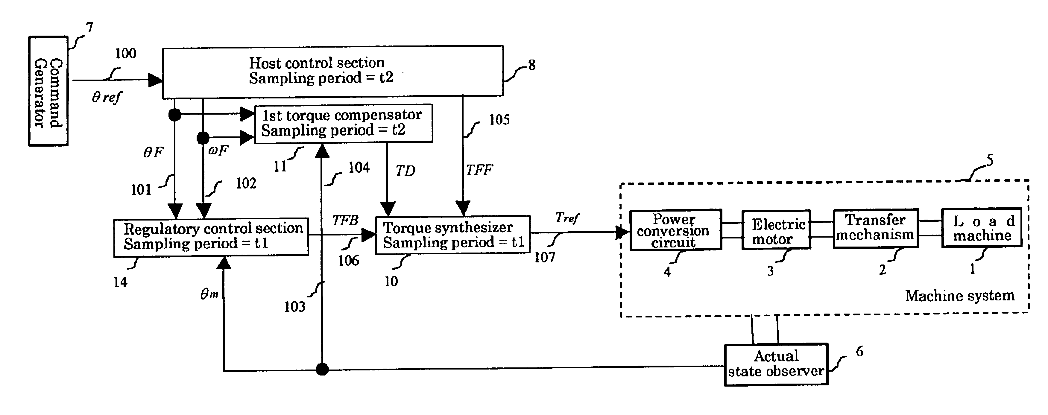
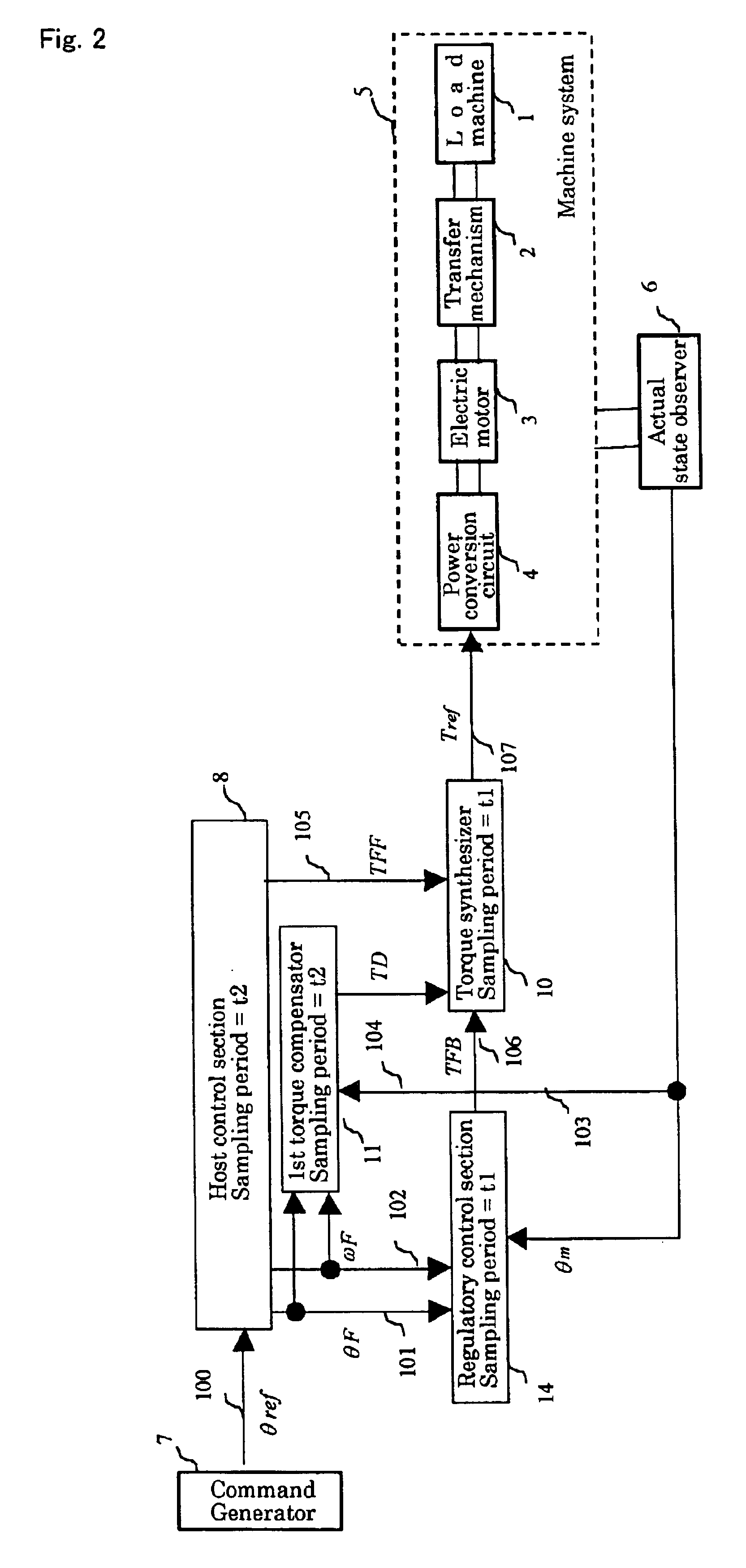
We next refer to FIG. 2 regarding the details of working example 1 of the present invention.
FIG. 2 is a block diagram showing an overall view of working example 1 of the present invention. In FIG. 2, the working example of the present invention comprises: machine system 5 comprising load machine 1, transfer mechanism 2, electric motor 3, and power conversion circuit 4; actual state observer 6, command generator 7, host control section 8, regulatory control section 9, torque synthesizer 10, and first torque compensator 11.
Machine system 5, actual state observer 6, and command generator 7 are identical to the machine system, the rotation detector and the command generator of prior-art devices, respectively. θref is an actual command signal that has been generated by command generator 7. θm is an actual response signal that has been generated by actual state observer 6.
Based on actual command signal θref, ...
working example 2
We next refer to FIG. 3 to describe the details of working example 2 of the present invention. FIG. 3 is a block diagram showing the overall configuration of the present working example. In FIG. 3, the working example of the present invention includes: machine system 5 that comprises load machine 1, transfer mechanism 2, electric motor 3, and power conversion circuit 4; actual state observer 6; command generator 7; host control section 8; regulatory control section 9; torque synthesizer 10; and second torque compensator 12.
Second torque compensator 12 provides third simulation torque signal TD with each second control sampling time t2 based on second simulation torque signal TFB.
In second torque compensator 12, third simulation torque signal TD is generated by expressing equation (7) below in the discrete-time representation with respect to second control sampling time period t2.
TD=K5*TFB / s (7)
working example 3
We next refer to FIG. 4 to describe details regarding working example 3 of the present invention.
FIG. 4 is a block diagram showing the overall configuration of this working example. In FIG. 4, the working example of the present invention includes: machine system 5 that comprises load machine 1, transfer mechanism 2, electric motor 3, and power conversion circuit 4; actual state observer 6; command generator 7; host control section 8; regulatory control section 14; torque synthesizer 10; simulation observer 13; and second torque compensator 12.
Simulation observer 13 provides estimated position signal θmh and estimated speed signal ωmh at first control sampling time t1 based on actual response signal θm and torque command Tref.
Regulatory control section 14 provides second simulation torque signal TFB with each first control sampling time period t1 based on first simulation position signal θF, first simulation speed signal ωF, estimated position signal θmh, and estimated speed signal ω...
PUM
 Abstract
Description
Claims
Application Information
 - R&D
- Intellectual Property
- Life Sciences
- Materials
- Tech Scout
- Unparalleled Data Quality
- Higher Quality Content
- 60% Fewer Hallucinations
Browse by: Latest US Patents, China's latest patents, Technical Efficacy Thesaurus, Application Domain, Technology Topic, Popular Technical Reports.
© 2025 PatSnap. All rights reserved.Legal|Privacy policy|Modern Slavery Act Transparency Statement|Sitemap|About US| Contact US: help@patsnap.com


