
Liquid crystal projection apparatus utilizing image synthesizing unit with liquid crystal panel holders

a liquid crystal projection and image synthesizer technology, applied in the direction of instruments, mountings, color television details, etc., can solve the problems of insatiable fixation of liquid crystal panel holders, prism pedestals, etc., and achieve the effect of reducing the number of parts and high assembling precision

Active Publication Date: 2012-01-31
SANYO ELECTRIC CO LTD +1
View PDF7 Cites 2 Cited by
  • Summary
  • Abstract
  • Description
  • Claims
  • Application Information

AI Technical Summary

Benefits of technology

The invention is a liquid crystal projection apparatus with image synthesizing means that has a reduced number of parts and high assembly precision. The apparatus includes a color synthesization prism, upper and lower prism pedestals, upper and lower liquid crystal panel holders, and three liquid crystal panels. The liquid crystal panel holders are independently fixed on the prism pedestals, which reduces the influence of precision errors and simplifies the assembly process. The apparatus also uses a single incident face for each jointing section, which further improves the accuracy of the assembly. The invention achieves high-quality colored imaging light and reduces the weight and cost of the image synthesizing means.

Problems solved by technology

However, such fixation of the liquid crystal panel holders 38b, 38g, and 38r to the prism pedestal 30 is not satisfactory for the following reasons.
First, each of the liquid crystal panel holders 38b, 38g, and 38r need be simultaneously assembled onto at least two sides (referred to as assembling faces) of the upper and lower prism pedestals 301 and 302, which will result in precision errors of the liquid crystal panel holders, which in turn causes deformations of the liquid crystal panel holders during their assembly, which deformations affects collimation of light by the optical system.
Such large deformations of the soldering joint sections directly affect the collimation of light.

Method used


Image

  • Liquid crystal projection apparatus utilizing image synthesizing unit with liquid crystal panel holders
  • Liquid crystal projection apparatus utilizing image synthesizing unit with liquid crystal panel holders
  • Liquid crystal projection apparatus utilizing image synthesizing unit with liquid crystal panel holders

Examples


Embodiment Construction

[0053]Referring to the accompanying drawings, a liquid crystal projection apparatus and relevant components thereof in accordance with the invention will now be described in detail. In what follows, the term “forward direction” refers to the direction of projecting an image by the image projection apparatus shown in FIG. 1, the term “right” refers to the right direction with reference to the forward direction. The terms “rear”, “bottom”, and “sides” of the apparatus are used in ordinary sense to refer to different sections of an apparatus of interest. Therefore, these terms may depend on how the apparatus is installed and used.

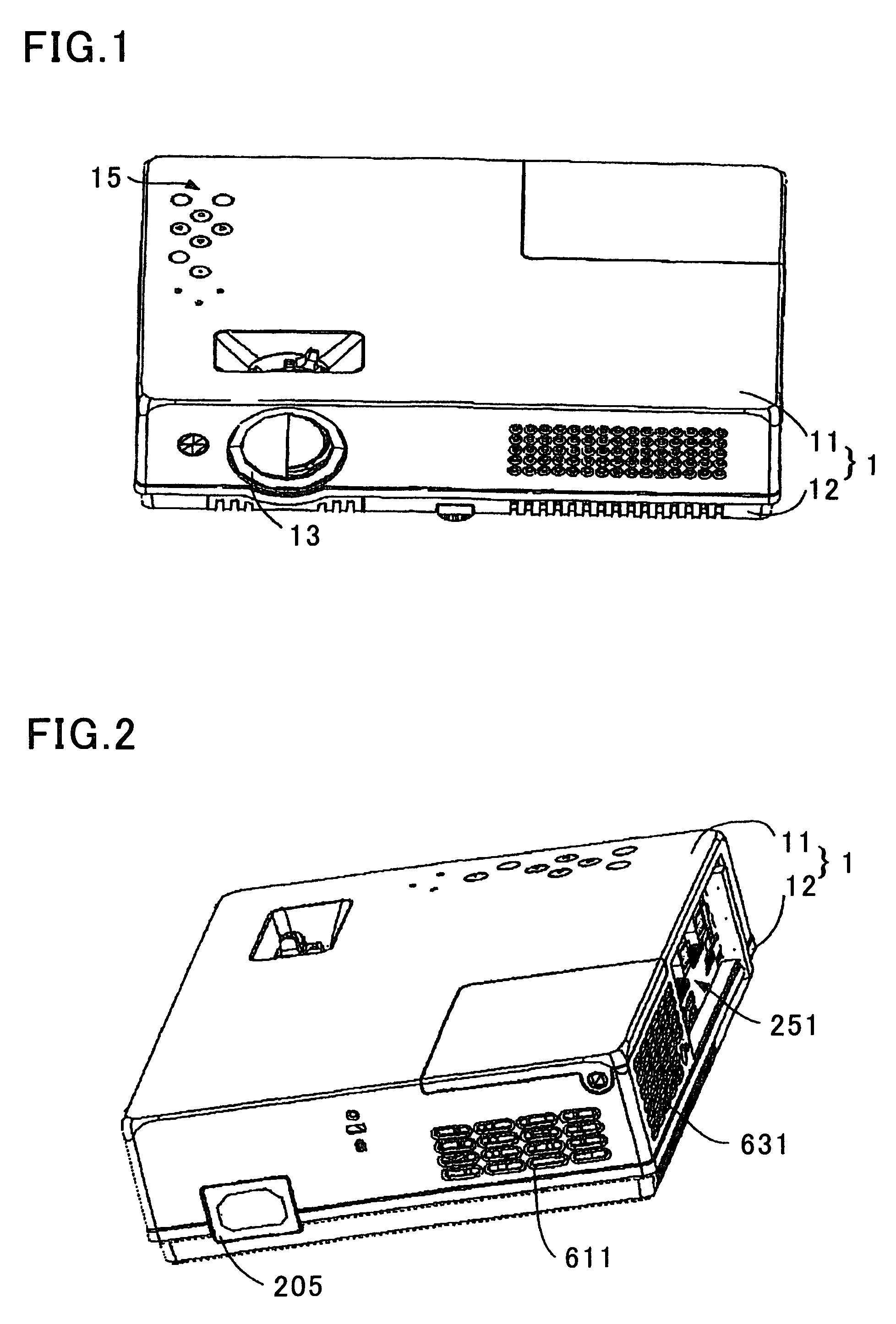
[0054]Referring to FIG. 1, there is shown a liquid crystal projection apparatus of the present invention having a casing 1 which consists of an upper case 11 and a lower half case 12. Provided on the top end of the casing 1 is a control section 15 having a multiplicity of manually operable buttons. Formed in the front end of the casing 1 is a projection window...


PUM

PropertyMeasurementUnit
weightaaaaaaaaaa
humidityaaaaaaaaaa
temperatureaaaaaaaaaa

Abstract

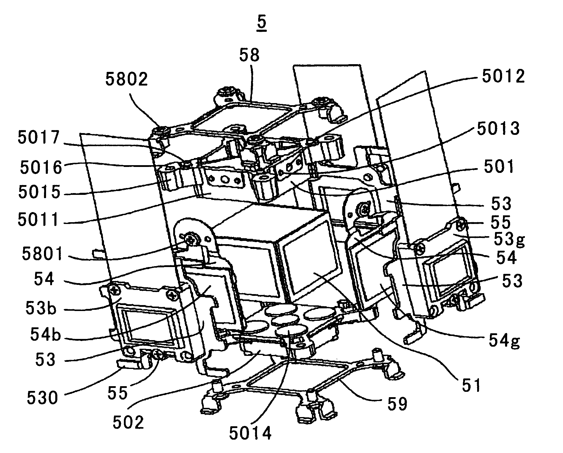
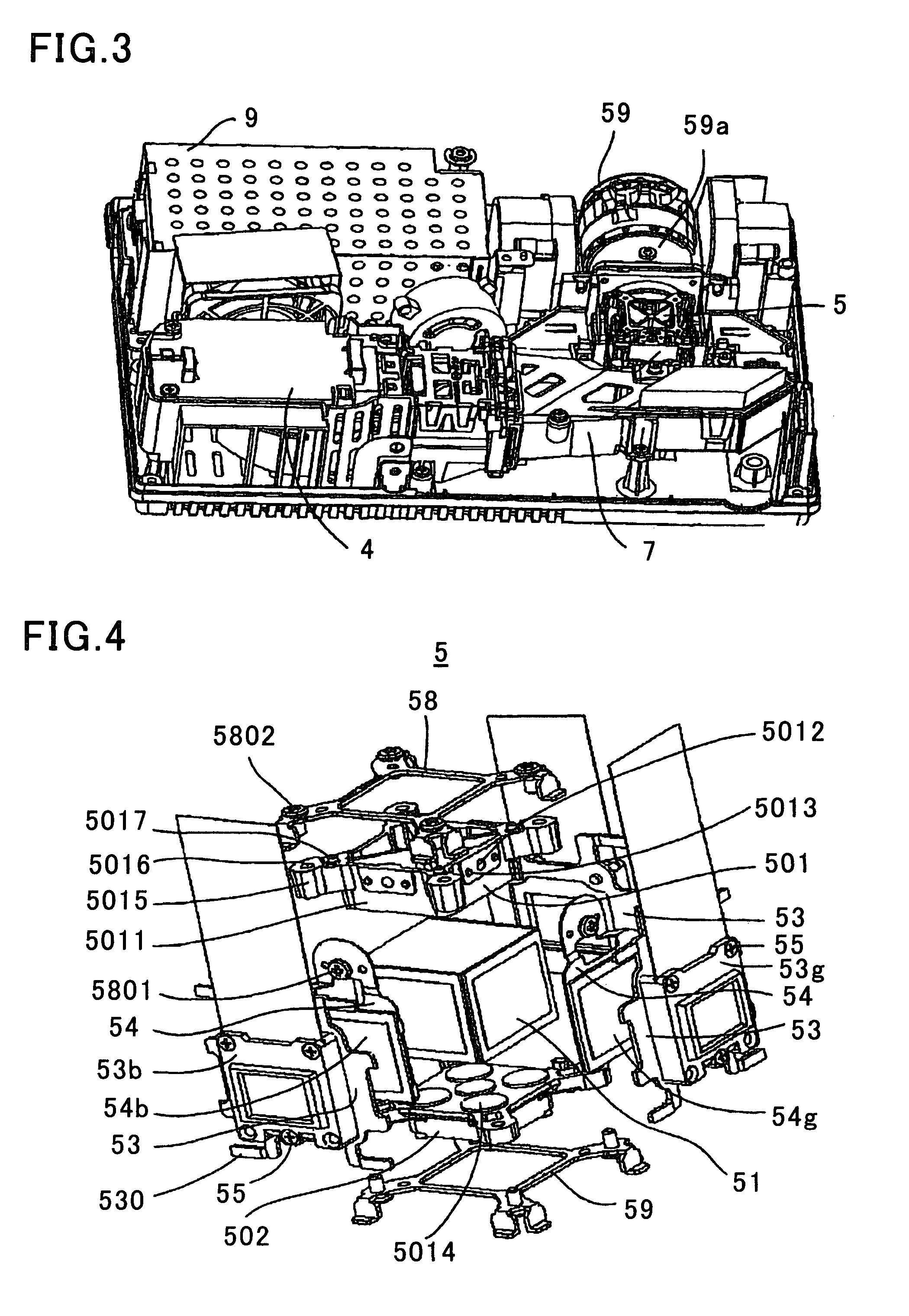
A liquid crystal projection apparatus having an image synthesizing unit including a color synthesization prism having an upper surface, a lower surface facing the upper surface, and three light incident faces between the upper and lower surfaces; an upper prism pedestal provided on the upper surface of the color synthesization prism; a lower prism pedestal provided on the lower surface of the color synthesization prism; an upper liquid crystal panel holder provided on the upper prism pedestal and having first jointing sections, a lower liquid crystal panel holder provided on the lower prism pedestal and having second jointing sections; three liquid crystal panels; and three liquid crystal panel mounting members securely fixing thereon the three liquid crystal panels, the three mounting members arranged on the respective three incident faces of the color synthesization prism joining the first jointing sections located in association with the respective incident faces to corresponding second jointing sections located in association with the corresponding incident faces.

Description

FIELD OF THE INVENTION[0001]This invention relates to a liquid crystal projection apparatus, and more particularly, to one utilizing image synthesizing means.BACKGROUND OF THE INVENTION[0002]Along with recent rapid development of light-weight low-cost projection apparatuses, development of image synthesization units (image synthesizing means) is underway, since image synthesization units are important parts of such projection apparatuses.[0003]For example, Chinese Utility Model No. 200620133278.7 discloses an image synthesization unit 3 coupled to an optical system 2 of a projection apparatus as shown in FIGS. 8 and 9.[0004]In this utility model, white light emitted from a lamp unit 4 is led to a first dichroic mirror 26 via a first integrator lens 21, pre-stage light-shielding lattice 23, second integrator lens 22, post-stage light-shielding lattice 24, polarization prism plate 25, and condenser lens 20.[0005]The first integrator lens 21 and the second integrator lens 22 each consi...

Claims


Application Information

Patent Timeline
Patent Type & Authority Patents(United States)
IPC IPC(8): G02F1/1335G03B21/26G03B21/00
CPCG02B7/1805H04N9/3105H04N9/315
Inventor ZHANG, XIANGLINWU, JIEYANGRENBUTSU, TADASHIOKAZAKI, SHOJIHUANG, YANSHAN
Owner SANYO ELECTRIC CO LTD
Learn More