Pressure compensation unit for use in a pressure sensor

a pressure sensor and compensation unit technology, applied in the field of pressure sensors, can solve the problems of affecting the function, affecting the accuracy of pressure measurement, and requiring a large installation space for pressure compensation units, so as to avoid capillary effects, facilitate and quickly produce, and prevent capillary effects

Active Publication Date: 2012-02-07
ROBERT BOSCH GMBH
View PDF8 Cites 16 Cited by
  • Summary
  • Abstract
  • Description
  • Claims
  • Application Information

AI Technical Summary

Benefits of technology

[0014]The housing of the pressure compensation unit may be designed, in particular, at least partially as a cover, i.e., as an element which is subsequently placed on and at least partially covers a sensor housing of a pressure sensor. The cover may thus completely or partially cover, for example, a reference pressure chamber which is entirely or partially accommodated in the sensor housing, and / or the cover may provide a portion of this reference pressure chamber. It is particularly preferable if the housing has at least one connecting element for a force-locking and / or form-locking connection of the cover to a sensor housing of the pressure sensor. In particular, this connecting element may include at least one clamping tab and / or at least one latching tab and / or at least one clamping opening and / or at least one latching opening, so that a clamp connection and / or a latch connection may be easily and quickly produced between the sensor housing and the cover in one assembly operation.
[0015]The channel is preferably provided with a cross section which prevents capillary effects. It is particularly preferable if the channel has a cross section of at least 2 mm2, in particular at least 10 mm2, preferably at last 20 mm2 and particularly preferably 50 mm2 or more. Furthermore, the channel may preferably have a length of at least 10 mm, preferably at least 15 mm or even at least 20 mm. However, other dimensions are also possible. In this way, the channel may provide, on the one hand, effective shielding of the opening and the filter diaphragm against the direct entry of contaminants and / or fluids, for example against water. On the other hand, the channel provides an adequate cross section for the inflow or outflow of gases to or from the opening during pressure compensation, while avoiding capillary effects.
[0017]The proposed pressure compensation unit and the proposed pressure sensor have numerous advantages over known pressure compensation units and pressure sensors. Thus, the filter diaphragm may act as a pressure compensation diaphragm and provide overload protection, since faster and more reliable pressure compensation may be carried out. The filter diaphragm itself is protected against overload and may simultaneously provide fast pressure compensation between an environment and the reference pressure chamber. Furthermore, the described pressure compensation unit may be implemented in a comparatively small installation space. In contrast, for example, to the design described in published German patent application DE 10 2008 004 358, the example embodiment of the present invention ordinarily requires only installation space with regard to height, but not to length. At the same time, a sufficiently large opening for a channel and / or tunnel may be provided, in which water is unable to accumulate and / or adhere thereto due to capillary effects. Dirt and dust are also unable to block the sufficiently large opening in the channel. This enables the pressure sensor to breathe at all times. The filter diaphragm, which may be designed as a pressure compensation diaphragm, is protected against mechanical damage by situating the opening over which the filter diaphragm is located within the channel, which may be designed as a tunnel. The filter diaphragm may be situated, for example, largely parallel to a direction of the longitudinal extension of the channel. However, other types of orientation are also possible, in principle.
[0018]Due to the design of the pressure compensation unit, in which the channel formed by the opening closed by the filter diaphragm is located inside a housing, for example a cover, the filter diaphragm is better protected against mechanical damage than in known designs. Due to the possible “stacked” configuration of the filter diaphragm, for example above the current cover, only a height of an installation space is increased, but not the length of the sensor element. Due to the design of the channel, for example as a straight or bent tunnel, it is possible to ensure that the channel is open on both sides so that water and / or fluid medium may flow out through this channel, thus leaving the opening free. For example, the opening may be situated on an upper side of the channel, i.e., on a side which is situated above the channel when the pressure sensor is in the installed state. This may ensure that contaminants flowing or streaming through the channel are unable to adhere to the opening or the filter diaphragm.
[0019]The housing, for example the cover, having the at least one integrated channel and the opening, may be manufactured comparatively easily. For example, known and cost-effective plastic molding methods may be used, such as plastic injection molding, for example. The housing may be manufactured in a single operation.

Problems solved by technology

A technical challenge of known pressure compensation units is the fact that pressure compensation units require a large installation space.
However, it is not possible to reduce the size in many cases, since size reductions may cause capillary effects to occur in the openings of the pressure compensation unit, through which liquids and / or contaminants, in turn, may collect in and adhere to the pressure compensation unit, which might impair the functionality.

Method used


Image

  • Pressure compensation unit for use in a pressure sensor
  • Pressure compensation unit for use in a pressure sensor
  • Pressure compensation unit for use in a pressure sensor

Examples


Embodiment Construction

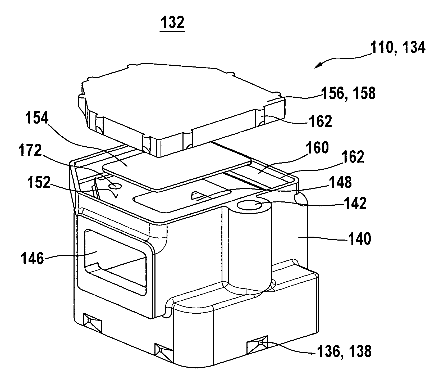
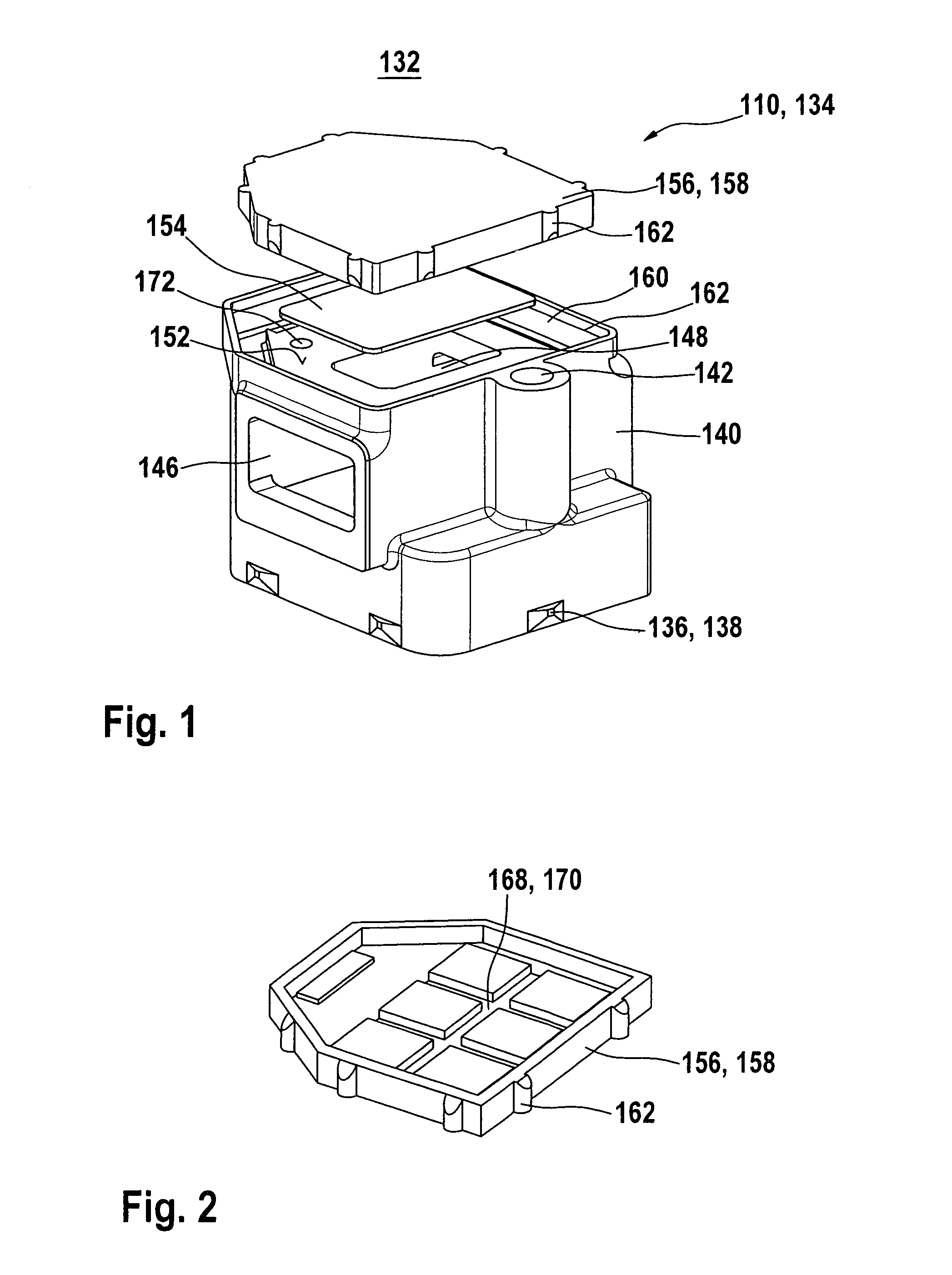
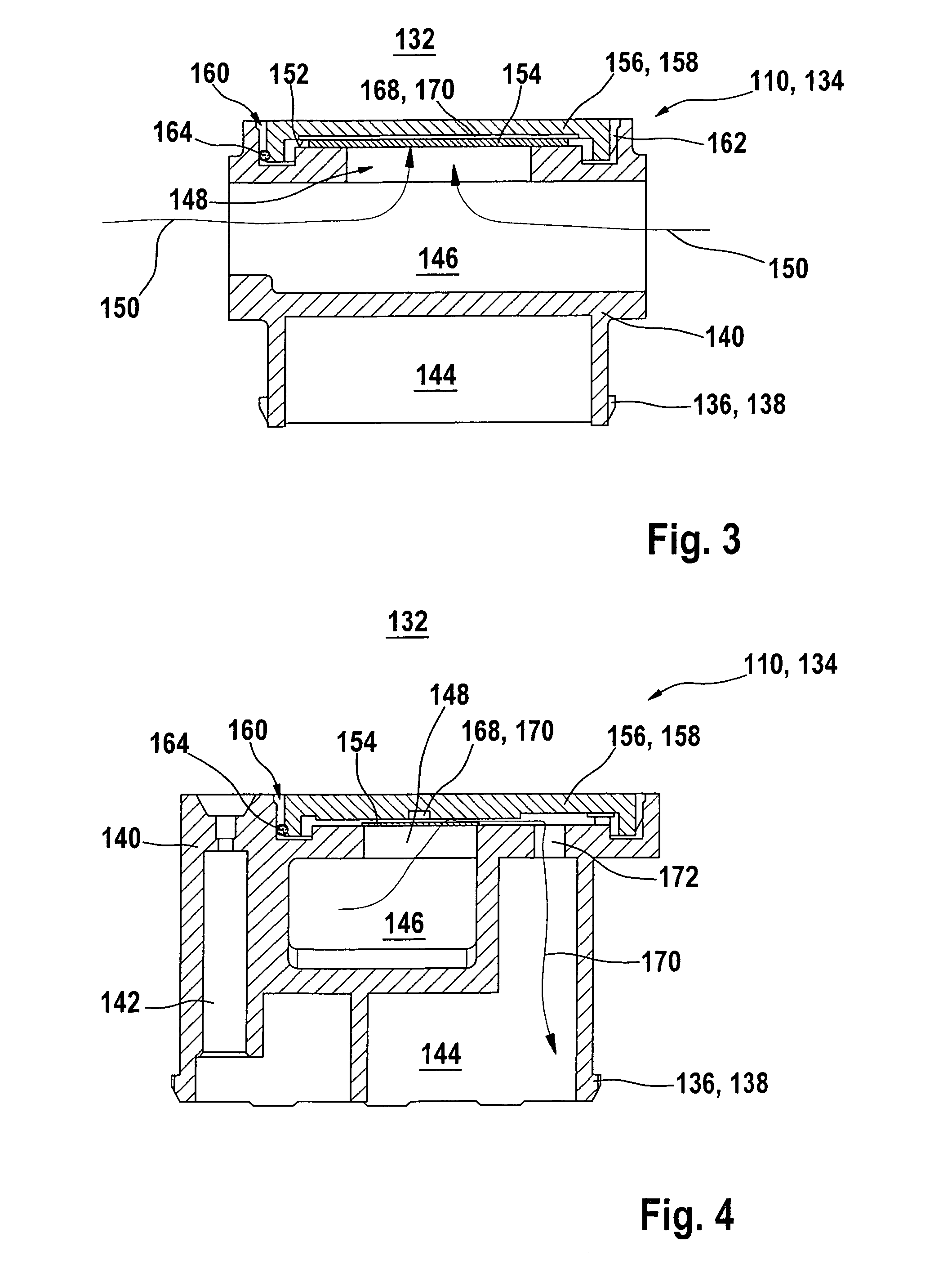
[0025]FIGS. 1 through 4 show different representations of an exemplary embodiment of a pressure compensation unit 110 according to the present invention by way of example. This pressure compensation unit may be used, for example, in a pressure sensor 112, which is shown in a perspective sectional representation in FIG. 5 and may be designed, in particular, as a fuel tank pressure sensor 114. Reference is made below to all figures, the functionality of pressure sensor 112 being described first on the basis of the representation in FIG. 5.

[0026]Pressure sensor 112 includes a sensor housing 116, which may be designed, for example, as an injection molded component. This component includes an electrical connector 118 for electrical contacting of pressure sensor 112. Pressure sensor 112 also has a connecting piece 120 having a measured pressure supply means 122 in the form of a pressure channel. Connecting piece 120 may be introduced into a wall of a measuring chamber 126, for example a f...


PUM

PropertyMeasurementUnit
lengthaaaaaaaaaa
lengthaaaaaaaaaa
lengthaaaaaaaaaa

Abstract

A pressure compensation unit for use in a pressure sensor includes a housing which has at least one continuous channel, at least one opening being provided in a wall of the channel. The opening is connectable to a reference pressure chamber of the pressure sensor via at least one air passage in the housing. The opening is closed by at least one gas-permeable and preferably fluid-tight filter diaphragm.

Description

BACKGROUND OF THE INVENTION[0001]1. Field of the Invention[0002]The present invention relates to pressure sensors for detecting a pressure of a fluid and / or a gaseous medium.[0003]2. Description of Related Art[0004]Pressure sensors of the above-noted type are known from a variety of applications. Reference is made below, in particular, to applications in automotive engineering, for example pressure cells for intake manifold or boost pressures, brake pressures, air spring pressures, tire pressures, hydraulic reservoir pressures, shock absorber pressures, coolant pressures, modulation pressures in automatic transmissions, brake pressures, fuel tank pressures, or combustion chamber pressures. Reference is made, in particular, to applications in fuel tank pressure sensors for motor vehicles. In principle, however, other automotive or non-automotive applications are also possible. For possible pressure sensors in automotive engineering, reference may be made to Robert Bosch GmbH: “Sensor...

Claims


Application Information

Patent Timeline
Patent Type & Authority Patents(United States)
IPC IPC(8): G01L19/04
CPCG01L19/0007G01L19/0636G01L19/142B60K15/03Y10T137/7837
Inventor HABIBI, MASOUDFESSELE, THOMAS
Owner ROBERT BOSCH GMBH
Why Eureka
Try Eureka