Converter gearing having eccentric bushes

a technology of eccentric bushes and gearing, which is applied in the direction of gearing, manufacturing converters, hoisting equipment, etc., can solve the problems of excessive wear of teeth, extreme loads per unit surface area, and high torque of the converter gear, so as to achieve the optimal adjustment of the backlash of the drive toothing, reduce load, and reduce the effect of backlash

Inactive Publication Date: 2012-02-07
SMS DEMAG AG
View PDF7 Cites 25 Cited by
  • Summary
  • Abstract
  • Description
  • Claims
  • Application Information

AI Technical Summary

Benefits of technology

[0012]The design of the support of the locking arm in accordance with the invention results in the great advantage that optimum adjustability of the backlash of the drive toothing of the gearing can be achieved at any time and independently of its production, and / or the backlash can be readjusted. This results in an even load distribution in the region of the locking teeth with about 5 to 6 tooth spaces of the region of engagement of the driven gear with drastically reduced load per unit surface area of the tooth flanks. The wear of the gear wheels of the gearing is reduced accordingly.

Problems solved by technology

Converter gears are subjected to high and variable torques during the oxygen-blowing operation.
These torques usually lead to extreme loads per unit surface area and thus to excessive wear of the teeth.
A disadvantage of this design is the required setting precision of the locking lever and its bearing, especially when two independent locking levers are installed.
This means that even small deviations from the ideal engagement position can lead to extremely high forces and stresses and thus to faster wear of the gear rim and the locking arm teeth.
This not only results in high production costs, but also has the further disadvantage that subsequent replacement or readjustment of the locking arm is not possible due to the special machining sequence.
It is readily apparent that this is an extremely expensive and complex arrangement that requires a considerably greater construction space.

Method used


Image

  • Converter gearing having eccentric bushes
  • Converter gearing having eccentric bushes
  • Converter gearing having eccentric bushes

Examples


Embodiment Construction

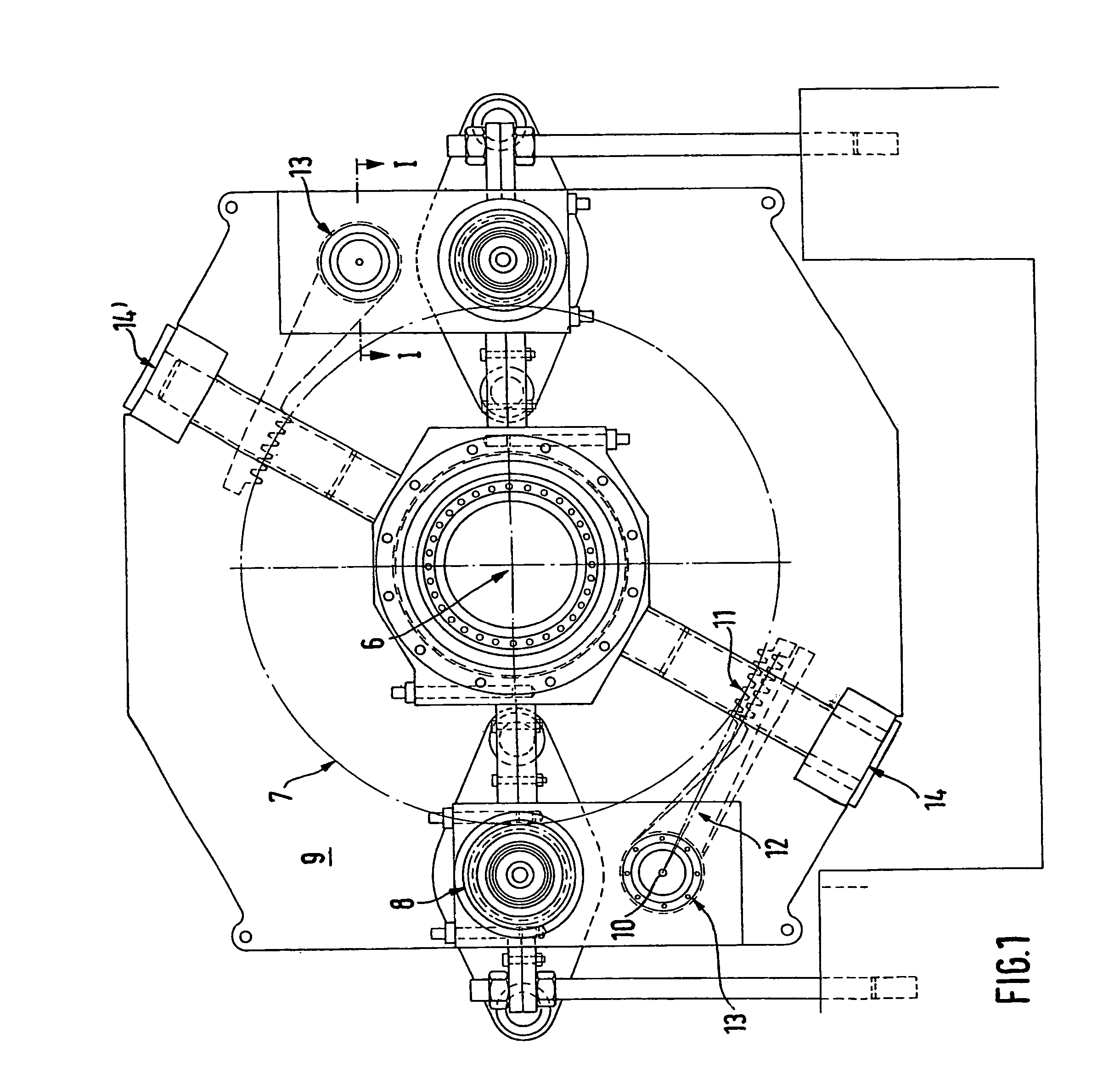
[0021]FIG. 1 shows a side view of converter gearing, which comprises a gear rim 7, which is connected to the axis of rotation 6 of a converter vessel (not shown) and engages at least one drive pinion 8 of the converter gearing 9, and at least one locking device, which can be swung in or out to engage with or disengage from the teeth of the gear rim 7 and has the form of a locking arm 12, which is mounted on a horizontal shaft 10, is configured with teeth 11 in its end region, and is rotatably supported.

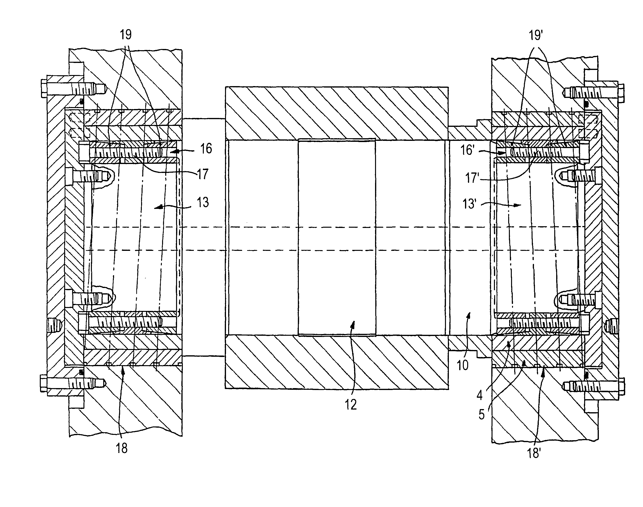
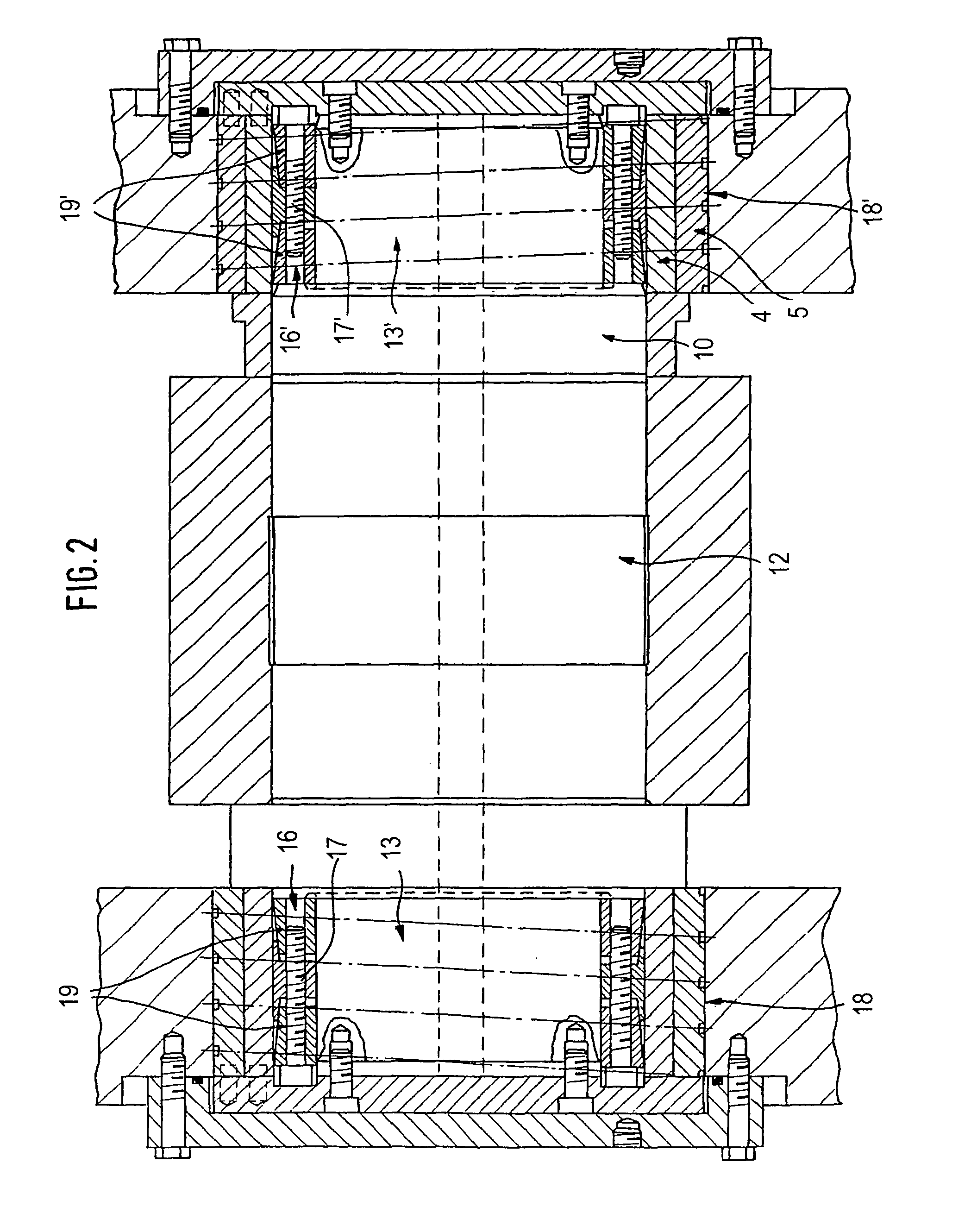
[0022]The locking arm 12 is supported with the shaft 10 in at least one terminal bearing 13, 13′ and can be nonpositively engaged with the teeth of the gear rim 7 or disengaged from the teeth of the gear rim 7 by means of active force elements 14, 14′, e.g., hydraulic cylinders, which preferably act on its end regions. The shaft 10 of the locking arm 12 is supported in the housing of the converter gearing 9 by two eccentric bushes 4, 5, which rotate freely, one within the other, at ea...


PUM

PropertyMeasurementUnit
inner diameteraaaaaaaaaa
diameteraaaaaaaaaa
diametersaaaaaaaaaa

Abstract

The invention relates to a converter gearing, comprising a gear rim (7), which is connected to the pivoting axis (6) of a converter box, said gear rim being engaged with at least one drive pinion (8) of the converter gearing (9) and at least one locking device, which can be pivoted to engage with and be disengaged from the toothed gearing of the gear rim, (7) in the form of a locking arm (12) that is positioned on a horizontal shaft (10) and configured with toothed gearing (11). The aim of the invention is to improve said locking device. To achieve this, the shaft (10) of the locking arm (12) is mounted in at least one terminal bearing (13, 13′) and the locking arm (12) can be engaged with and disengaged from the toothed gearing of the gear rim (7) in a non-positive manner, preferably by means of active force elements (14, 14′) in its end regions. In addition, the shaft (10) of the locking arm (12) is mounted in the housing of the converter gearing (9) by means of two eccentric bushes (4, 5), which rotate freely within one another, at each of its ends. The mounting is configured in such a way, that by the independent rotation of the same, an ideal mutual engagement position of the two interacting toothed gearing regions of the locking device (12) and the gear rim (7) can be set.

Description

BACKGROUND OF THE INVENTION[0001]The invention concerns converter gearing, which comprises a gear rim, which is connected to the axis of rotation of a converter vessel and engages at least one drive pinion of the converter gearing, and at least one locking device, which can be swung in or out to engage with or disengage from the teeth of the gear rim and has the form of a locking arm, which is mounted on a horizontal shaft and is configured with teeth, wherein the shaft is supported in a terminal bearing, the locking arm can be nonpositively engaged with or disengaged from the teeth by active force elements, e.g., hydraulic cylinders, and the shaft is supported in the housing of the converter gearing by two eccentric bushes, which rotate freely, one within the other, at each end of the shaft, in such a way that an ideal engagement position of the interacting toothed regions of the locking device and the gear rim can be set by independent rotation of the eccentric bushes, and a clamp...

Claims


Application Information

Patent Timeline
Patent Type & Authority Patents(United States)
IPC IPC(8): F16D9/06F16C35/00F16C17/26C21C5/46C21C5/50F16C23/02F16H35/00
CPCC21C5/4633C21C5/50Y10T74/19642
Inventor WURM, GERHARDSUNDERMANN, CHRISTOPHGRIMMEL, RUDIGER
Owner SMS DEMAG AG
Why Eureka
Try Eureka