Suction-recirculation device for stabilizing particle flows within a solar powered solid particle receiver

a solid particle receiver and suction recirculation technology, which is applied in solar heat systems, solar thermal energy generation, lighting and heating apparatus, etc., can solve the problems of destabilizing the particle curtain and ejecting particles, and achieve the effect of minimizing heat loss and high receiver efficiency

Active Publication Date: 2012-02-07
NAT TECH & ENG SOLUTIONS OF SANDIA LLC
View PDF2 Cites 60 Cited by
  • Summary
  • Abstract
  • Description
  • Claims
  • Application Information

AI Technical Summary

Benefits of technology

[0013]The present invention relates to suction-recirculation device for stabilizing the flow of a curtain of blackened heat absorption particles falling inside of a solar receiver with an open aperture. The curtain of particles absorbs the concentrated heat from a solar mirror array reflected up to the receiver on a solar power tower. External winds entering the receiver at an oblique angle can destabilize the particle curtain and eject particles. A fan and ductwork is located behind the back wall of the receiver and sucks air out through an array of small holes in the back wall. Any entrained particles are separated out by a conventional cyclone device. Then, the air is recirculated back to the top of the receiver by injecting the recycled air through an array of small holes in the receiver's ceiling and upper aperture front wall. Since internal air is recirculated, heat losses are minimized, and high receiver efficiency is maintained. Suction-recirculation velocities in the range of 1-5 m / s are sufficient to stabilize the particle curtain against external wind speeds in excess of 10 m / s.

Problems solved by technology

External winds entering the receiver at an oblique angle can destabilize the particle curtain and eject particles.

Method used


Image

  • Suction-recirculation device for stabilizing particle flows within a solar powered solid particle receiver
  • Suction-recirculation device for stabilizing particle flows within a solar powered solid particle receiver
  • Suction-recirculation device for stabilizing particle flows within a solar powered solid particle receiver

Examples


Embodiment Construction

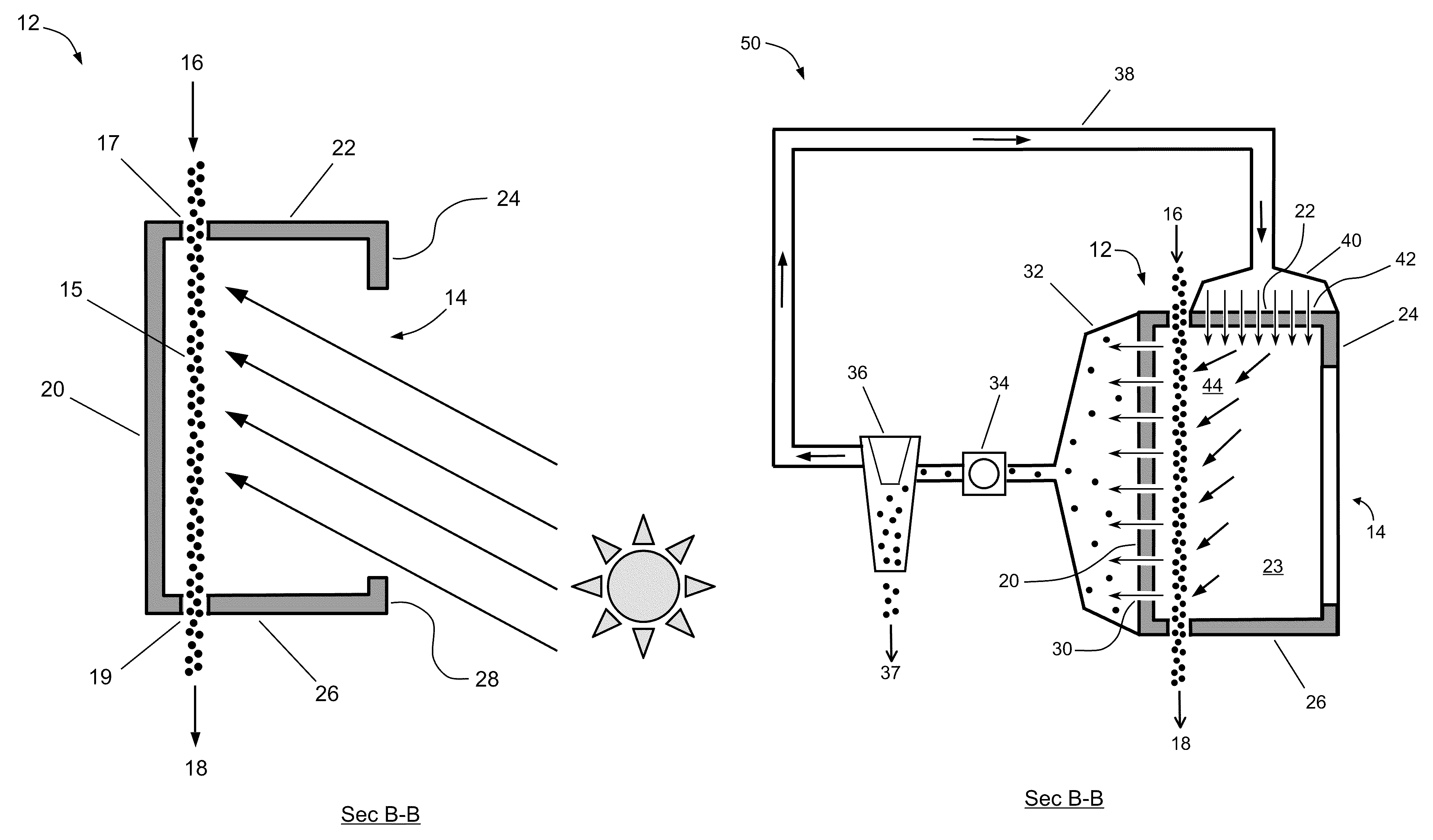
[0031]The words “cavity”, “receiver”, “receiver cavity” and “box” are used interchangeably.

[0032]The method and apparatus of the present invention is a suction-recirculation device that sucks air out of, and recirculates air back into, a solar-powered solid particle receiver cavity (box). This recirculation loop creates a modified internal airflow pattern (sweeping flow) within the receiver that stabilizes the particle curtain against disruption from oblique external wind flows. A fan (or fans) is installed within ductwork located behind the back wall of the cavity. The fan creates a negative pressure, and sucks the internal cavity air through many small holes that are evenly spaced along the back wall. This air is then recirculated and reintroduced back into the cavity through many small holes located in the cavity ceiling and the upper aperture front wall (i.e., top front lip of the cavity). Flow areas are matched so the mass flow rate of air flowing through the back wall is the s...


PUM


Abstract

A suction-recirculation device for stabilizing the flow of a curtain of blackened heat absorption particles falling inside of a solar receiver with an open aperture. The curtain of particles absorbs the concentrated heat from a solar mirror array reflected up to the receiver on a solar power tower. External winds entering the receiver at an oblique angle can destabilize the particle curtain and eject particles. A fan and ductwork is located behind the back wall of the receiver and sucks air out through an array of small holes in the back wall. Any entrained particles are separated out by a conventional cyclone device. Then, the air is recirculated back to the top of the receiver by injecting the recycled air through an array of small holes in the receiver's ceiling and upper aperture front wall. Since internal air is recirculated, heat losses are minimized and high receiver efficiency is maintained. Suction-recirculation velocities in the range of 1-5 m / s are sufficient to stabilize the particle curtain against external wind speeds in excess of 10 m / s.

Description

FEDERALLY SPONSORED RESEARCH[0001]The United States Government has rights in this invention pursuant to Department of Energy Contract No. DE-AC04-94AL85000 with Sandia Corporation.CROSS-REFERENCE TO RELATED APPLICATIONS[0002]NoneBACKGROUND OF THE INVENTION[0003]The present invention relates generally to a method and apparatus for collecting and transferring solar heat energy concentrated by an array of mirrors (heliostats).[0004]Solar power tower systems use an array of several thousand heliostats to focus sunlight onto a central receiver mounted on top of a tower. When heat is collected at a temperature of >900° C. it can be used to power a thermo-chemical cycle that produces hydrogen at a much lower cost than conventional solar electrolysis. The leading candidate for the 900° C. solar receiver is known as the Solid Particle Receiver. In this receiver concept (illustrated in FIGS. 1-3) originally proposed by Sandia California in the mid-1980's, blackened alumina particles (the s...

Claims


Application Information

Patent Timeline
Patent Type & Authority Patents(United States)
IPC IPC(8): F24J2/00
CPCF24J2/07Y02E10/41F24S20/20Y02E10/40
Inventor KOLB, GREGORY J.
Owner NAT TECH & ENG SOLUTIONS OF SANDIA LLC
Why Eureka
Try Eureka