Dispay panel and display apparatus

a display panel and display element technology, applied in the field of display panel and display element, can solve the problems of deterioration of display performance, light leakage, deterioration of aperture ratio of display element, etc., and achieve the effect of wide viewing angle, preventing light leakage, and higher speed response property

Active Publication Date: 2012-02-07
SHARP KK
View PDF61 Cites 6 Cited by
  • Summary
  • Abstract
  • Description
  • Claims
  • Application Information

AI Technical Summary

Benefits of technology

[0040]Moreover, in order to prevent the light leakage as mentioned above, Patent Document 4 discloses that a counter electrode and a pixel electrode are provided on a lower substrate of a pair of substrates on which external surfaces polarizers are bonded. Patent Document 4 also discloses that, in the liquid crystal element whose scanning line and data signal line are formed further on the lower substrate, a rubbing direction of the lower substrate is arranged to be identical to (i) a direction of an electric field (noise field) between the data signal line and the pixel electrode or counter electrode, and (ii) a direction of an electric field between the scanning signal line and the pixel electrode or counter electrode. In other words, in this technology, prevention of light leakage, in a case where a noise field occurs, is attempted by making the rubbing direction identical with the direction of the noise field. Furthermore, by preventing light leakage due to the noise field, it is not necessary to provide, for preventing light leakage, a black matrix layer over a wide area. This can increase an aperture ratio relatively.
[0086]A display apparatus of the present invention includes the display panel described above. Therefore, the display apparatus of the present invention can realize a high transmissivity property, a high-speed response property, and a wide viewing angle property.

Problems solved by technology

This causes a problem of deterioration in display performance.
This causes light leakage.
However, when a black matrix is formed so as to cover the region where light leaks, an aperture ratio of the display element deteriorates.
This causes a problem such that the power consumption increases because it becomes necessary to use a strong backlight for obtaining an appropriate brightness.

Method used


Image

  • Dispay panel and display apparatus
  • Dispay panel and display apparatus
  • Dispay panel and display apparatus

Examples


Embodiment Construction

[0138]One embodiment of the present invention is explained below.

[0139](1. Configuration of Display Panel 70)

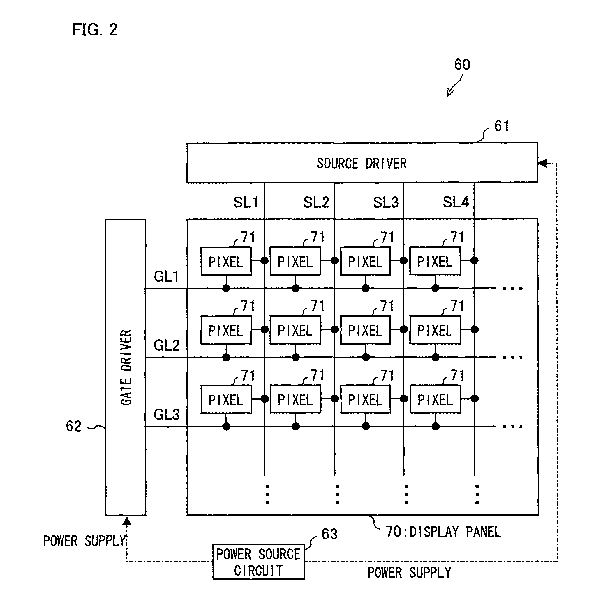
[0140]FIG. 2 is a block diagram illustrating a schematic configuration of various parts of a display apparatus 60 according to the present embodiment. FIG. 3 is a schematic diagram schematically illustrating a configuration of a pixel 71 in a display panel 70 in accordance with the present embodiment. The display apparatus 60 includes the display panel (display element) 70 as well as driving circuits, data signal lines, scanning lines, switching elements, and the like.

[0141]As illustrated in FIG. 2, the display apparatus 60 according to the present embodiment is provided with a display panel 70 in which pixels 71 are arranged in a matrix, a source driver 61 and a gate driver 62 as driving circuits, a power source circuit 63, and the like.

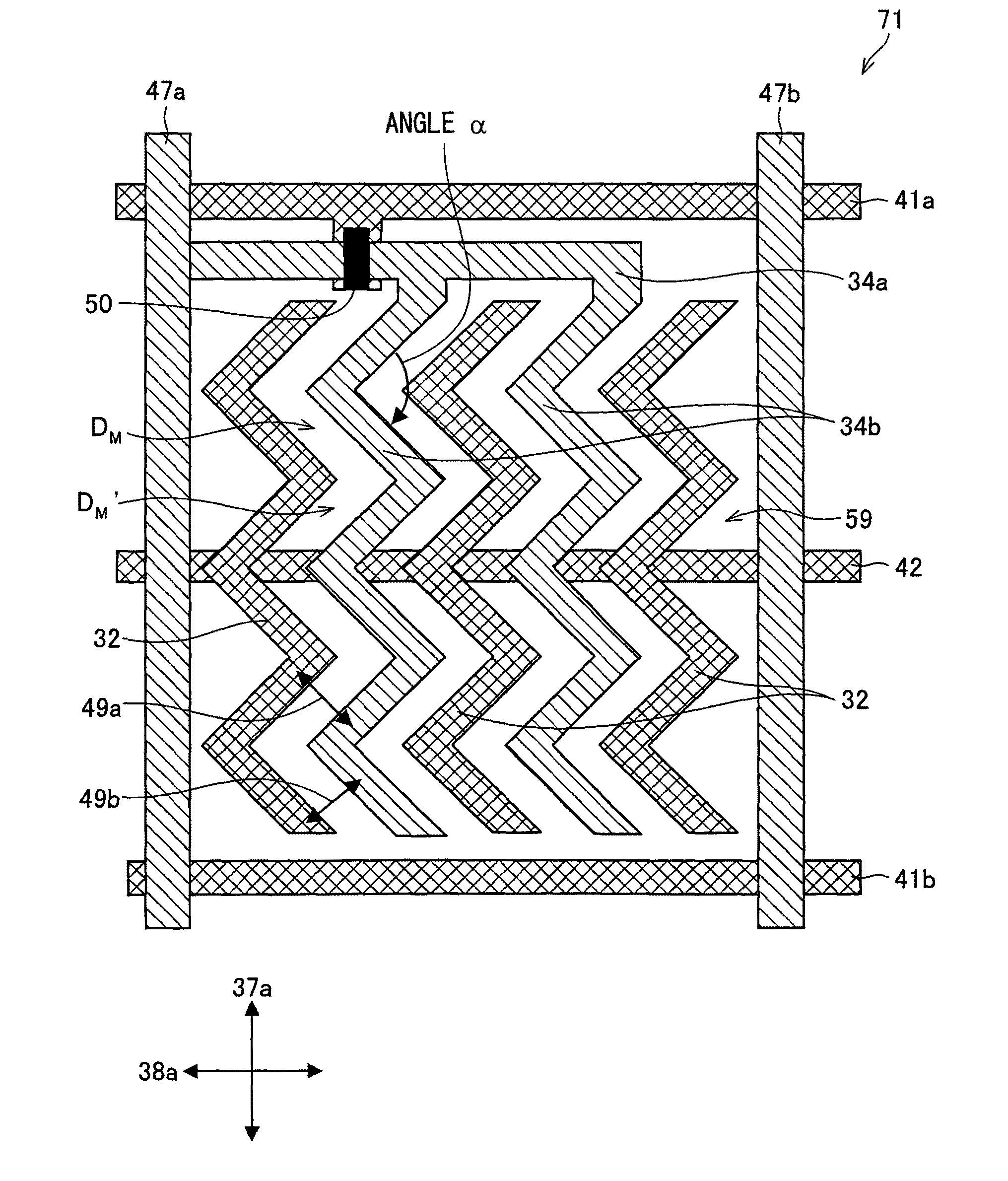
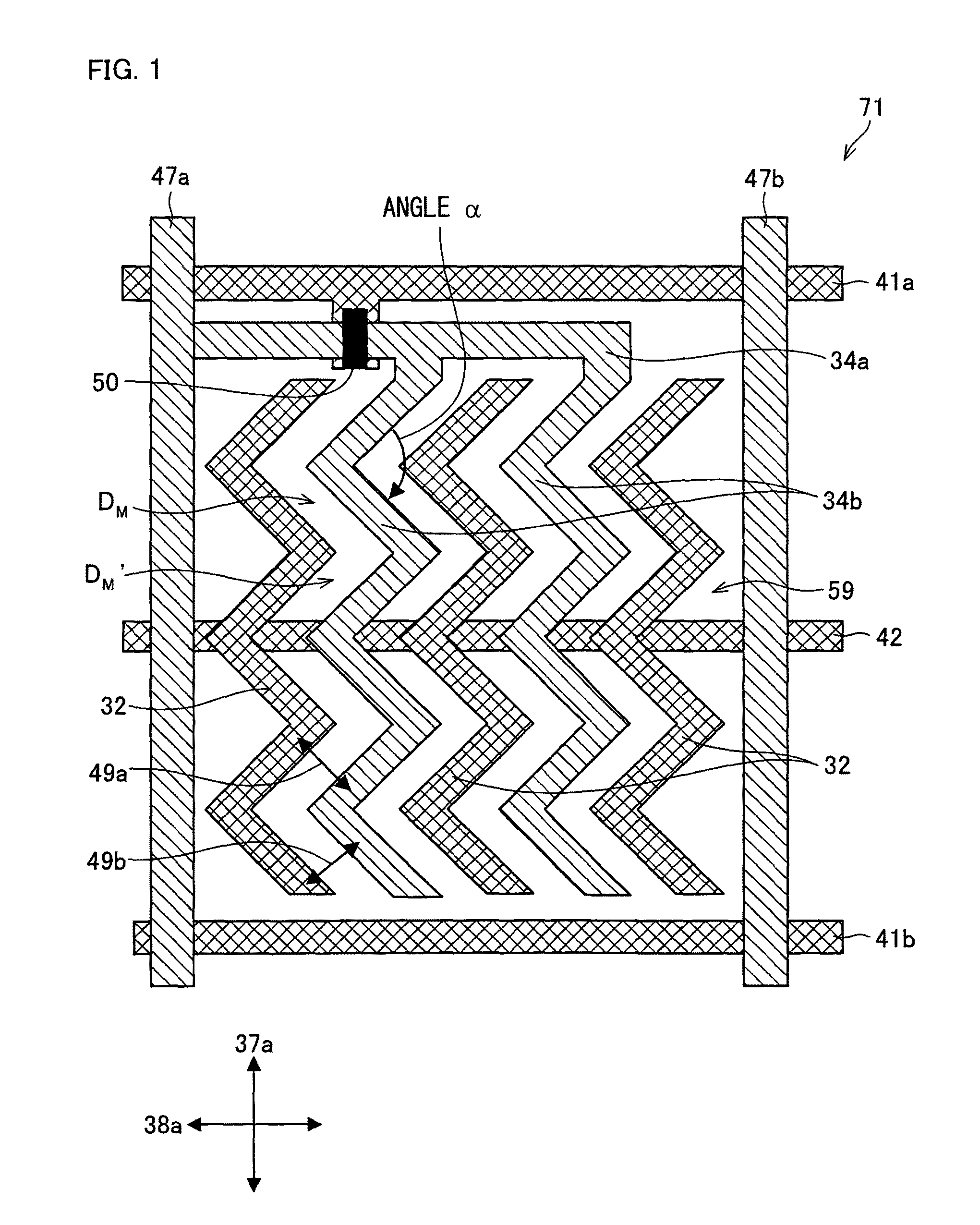
[0142]Each pixel 71 is, as illustrated in FIG. 3, provided with a pixel capacitor 120 and a switching element 50.

[0143]Moreover, the display...


PUM

PropertyMeasurementUnit
selective reflection wavelength bandaaaaaaaaaa
widthsaaaaaaaaaa
selective reflection wavelengthaaaaaaaaaa

Abstract

Scanning signal lines (41) and data signal lines (47) are arranged so as to cross each other, and common signal lines (42) and the scanning signal lines (41) are arranged to be parallel to each other. Moreover, a polarlizer (37) provided to an upper substrate (36) and a polarlizer (38) provided to a lower substrate (30) are arranged such that absorption axial directions (37a) and (38a) cross at an angle that is orthogonal. Moreover, the absorption axial directions (37a) and (38a) are arranged so as to be perpendicular to or parallel to directions in which the data signal lines (47), the scanning signal lines (41), and the common signal lines (42) are extended, respectively. This realizes an improved response speed and an increased transmissivity.

Description

[0001]This application is the U.S. national phase of International Application No. PCT / JP2006 / 311960, filed 14 Jun. 2006, which designated the U.S. and claims priority to Japanese Patent Application No. 2005-272617, filed 20 Sep. 2005, the entire contents of each of which are hereby incorporated by reference.TECHNICAL FIELD[0002]The present invention relates to a display panel and a display apparatus, which are highly transmissive, can respond at a high speed, and has a wide viewing angle.BACKGROUND ART[0003]Liquid crystal display elements are display elements having a thin thickness, a light weight, and a low power consumption among various display elements. This leads to wide application of liquid crystal display elements to, for example, image display apparatuses such as televisions, and OA (Office Automation) apparatuses such as personal computers.[0004]Conventionally known liquid crystal display methods (display mode) of the liquid crystal display elements include, for example,...

Claims


Application Information

Patent Timeline
Patent Type & Authority Patents(United States)
IPC IPC(8): G02F1/1335
CPCG02F1/134309G02F1/134363G02F1/1337
Inventor SHIBAHARA, SEIJI
Owner SHARP KK
Why Eureka
Try Eureka