Slider for a fluid tight slide fastener

a fluid tight and slide technology, applied in the direction of slide fasteners, fastenings, press-button fasteners, etc., can solve the problems of not being reliably moulded and adding significantly to the production process, so as to reduce the production process cost and improve product quality

Active Publication Date: 2012-02-14
YKK CORP
View PDF23 Cites 84 Cited by
  • Summary
  • Abstract
  • Description
  • Claims
  • Application Information

AI Technical Summary

Benefits of technology

[0008]Thus a first aspect of the present invention provides a slider for a fluid tight slide fastener, the slider having upper and lower plates joined together by a guide post and a guide plate formed on the guide post to cooperate with the upper and lower plates to guide the coupling elements and sealing lips of the slide fastener, wherein the slider is integrally formed. In particular the slider may be die cast or moulded as a single, integral member of metal or plastics material. By integrally forming the slider we are able to strengthen the slider, and in particular in the region between the upper plate and the guide plate where the slider parts are subject to greater separation forces as the slider is pulled along the fastener to urge the sealing lips together. This substantially reduces the cost of the production process and also leads to an improvement in product quality because of the avoidance of any misalignment or other errors which may arise in an assembly process.

Problems solved by technology

This adds significantly to the cost of the production process.
A difficulty with the prior art slider design was the use of a relatively thin guide plate which extended a relatively long distance from the guide post and so was unsupported.
This could not be reliably moulded as an integral part of the slider.

Method used


Image

  • Slider for a fluid tight slide fastener
  • Slider for a fluid tight slide fastener
  • Slider for a fluid tight slide fastener

Examples


second embodiment

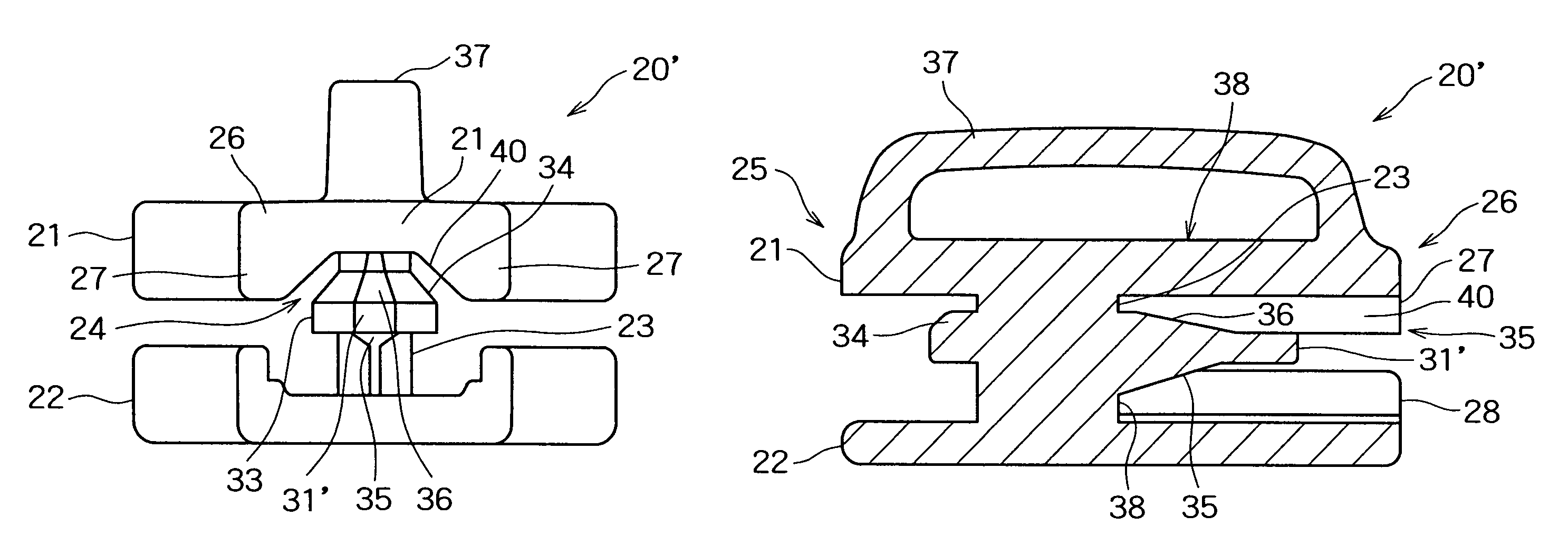
[0038]FIGS. 8 to 10 show the invention, similar to the embodiment of FIGS. 4 to 7 and like parts are given like reference numerals. In this embodiment, the web 29 of the previous embodiment is omitted. However, the thickness of the forward portion 32 is continued rearward past the trailing edge 39 of the guide post 23 and tapers down in thickness to a trailing edge 31′ which is thinner than the forward portion 32 to thus form on the trailing portion 30 of the guide plate 24 a trailing surface 36 which slants down toward the trailing edge 31′ of the guide plate 24. The opposed lateral sides of the trailing surface 36 merge in the chamfer 34 provided on the forward and side portions 32, 33. On the trailing portion 30 is formed a sticklike nose portion 30a extending from the trailing surface 36 toward the trailing end 26 of the slider 20.

[0039]Also shown in this second embodiment is the provision of fillets 40 between the upper side flanges 27 and the upper plate 21 to form an outlet m...

third embodiment

[0041]FIGS. 11 and 12 show the present invention. The third embodiment is similar to the second embodiment shown in FIGS. 8 through 10. So, parts which are similar to those of the second embodiment shown in FIGS. 8 through 10 are also denoted by the same reference numerals in FIGS. 11 and 12 showing the third embodiment. In the third embodiment, the trailing surface 36 formed on the trailing portion 30 of the guide plate 24 extends to the trailing edge 31 of the guide plate 24. Furthermore, the trailing portion 30 tapers in width or lateral dimension towards the trailing end 26 of the slider 1, thus presenting a wedge-like shape as a whole. This ensures that the sealing lips 11 can pass smoothly through the slider 1 during the movement of the slider 1, thereby mitigating frictional resistance caused by the sealing lips' sliding movement against the guide plate 24.

Conclusions, Ramifications, and Scope

[0042]As above stated, since the slider is integrally formed, the slider can be stre...


PUM


Abstract

A slider for a fluid tight slide fastener that has upper and lower plates joined together by a guide post. A guide plate is formed on the guide post to cooperate with the upper and lower plates, to guide the coupling elements and sealing lips of the slide fastener into engagement in conjunction with side flanges on the upper and lower plates. The slider is integrally formed, such as by die casting or moulding. To facilitate moulding the guide plate may be thickened at its leading end and provided with a tapered edge, and connected to the upper plate by a web at its trailing end.

Description

CROSS-REFERENCE TO RELATED APPLICATIONS[0001]The entire disclosure of British patent application No. GB0618329.7 filed on Sep. 18, 2006 is incorporated herein by reference in its entirety.BACKGROUND[0002]1. Field of the Invention[0003]This invention relates to a slider for a fluid tight fastener.[0004]2. Description of the Related Art[0005]Examples of such a fluid tight fastener are described in EP-A-1057423 and EP-A-1175842. In such a fluid tight fastener, a coil like continuous coupling member is sewn onto a tape surface near an edge of the tape. The other surface of the tape is coated with a fluid proof layer which extends beyond the edge of the tape to form a sealing lip. When the coupling members of adjacent tapes are engaged, the sealing lips of the fluid proof layers abut to form a seal. Such fasteners can provide a reasonably good seal against liquids or gasses, depending on various factors such as the design of the sealing lips of the fluid proof layers, the extent to which...

Claims


Application Information

Patent Timeline
Patent Type & Authority Patents(United States)
IPC IPC(8): A44B19/10
CPCA44B19/26Y10T24/2514Y10T24/2588Y10T24/264Y10T24/2561Y10T24/2582Y10T24/2584
Inventor TAKAZAWA, SHIGEYOSHIYONEOKA, MORIMASA
Owner YKK CORP
Why Eureka
Try Eureka