
Piezoelectric microphone, speaker, microphone-speaker integrated device and manufacturing method thereof

a technology of integrated devices and microphones, applied in the direction of deaf-aid sets, electrical transducers, electrical instruments, etc., can solve the problems of low output of micro-speakers and relatively low sensitivity of microphones

Active Publication Date: 2012-02-14
ELECTRONICS & TELECOMM RES INST
View PDF20 Cites 17 Cited by
  • Summary
  • Abstract
  • Description
  • Claims
  • Application Information

AI Technical Summary

Benefits of technology

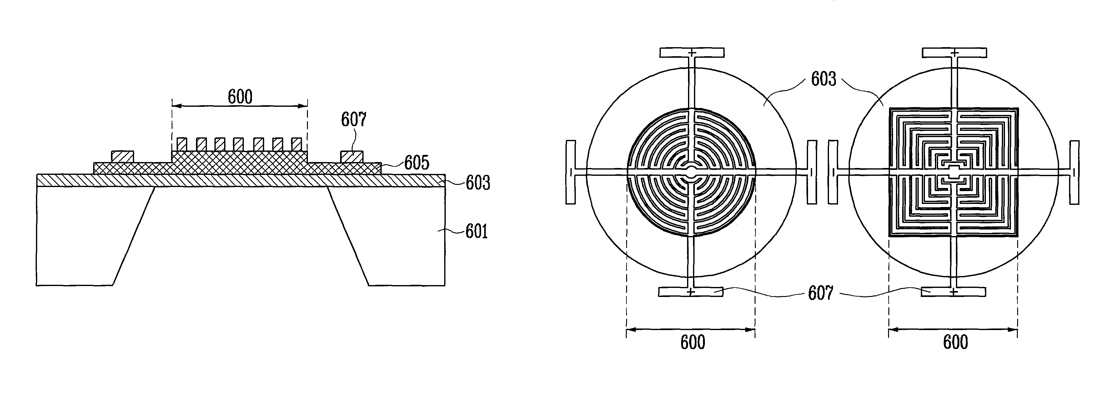
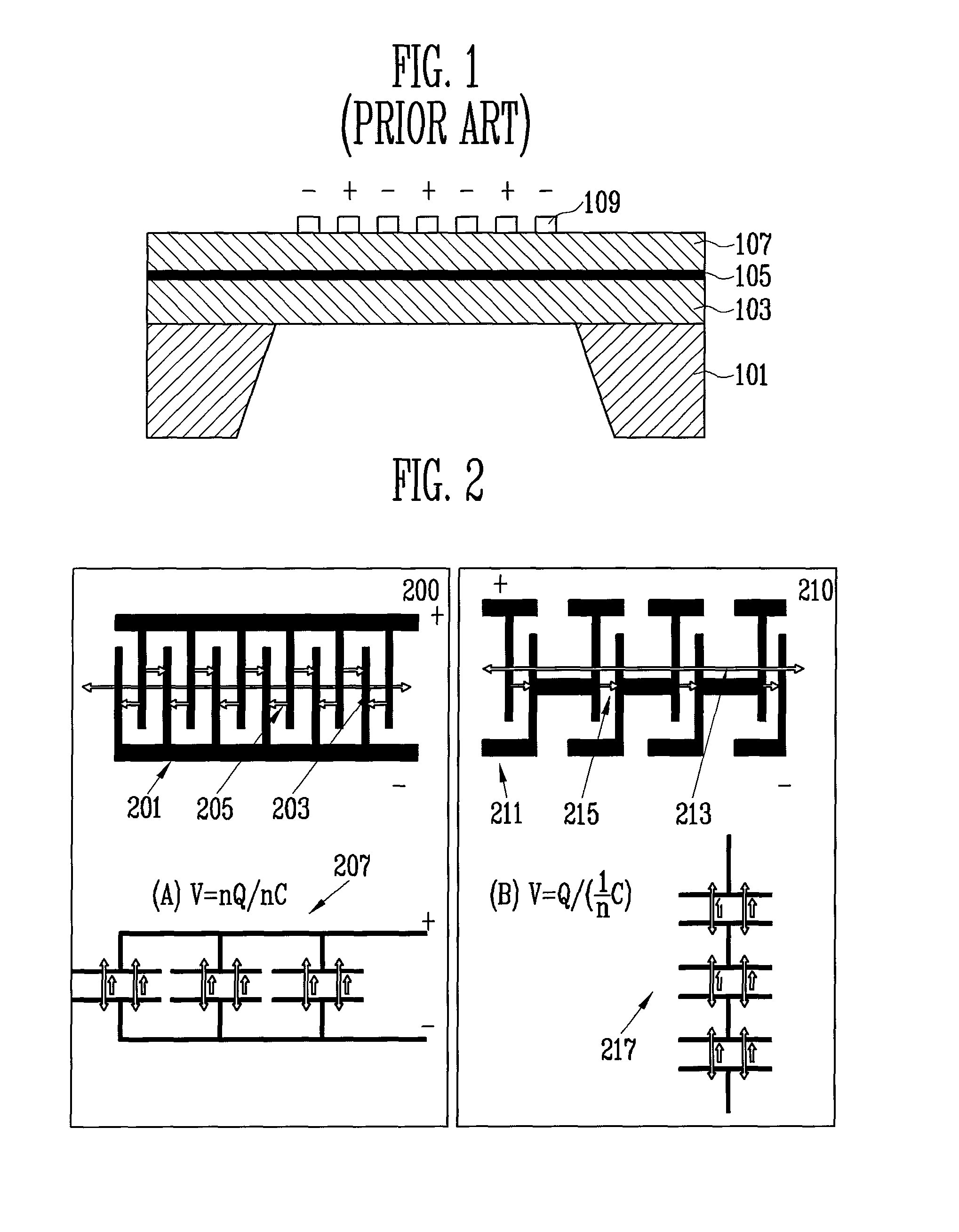
The present invention is about a piezoelectric microphone and speaker, and a method of manufacturing them. The microphone has a mating electrode pattern arrayed in series, and the speaker has a differentially etched piezoelectric plate and a series / parallel mating electrode pattern. The piezoelectric plate is either adhered using an epoxy series adhesive or deposited using a sol-gel method. The piezoelectric plate may include a single layer or a multi-layer of piezoelectric material. The mating electrode is patterned on at least one of an outer circumference and a center of the piezoelectric plate. The piezoelectric speaker includes a silicon substrate and an insulating layer deposited on the silicon substrate, with the piezoelectric plate being differentially etched with respect to the mating electrode and an outer circumferential portion. The method of manufacturing the piezoelectric microphone includes depositing an insulating layer on a silicon substrate, forming a piezoelectric plate on the insulating layer, and patterning a mating electrode on the piezoelectric plate. The method of manufacturing the piezoelectric speaker includes depositing an insulating layer on a silicon substrate, forming a piezoelectric plate on the insulating layer, and differentially etching the piezoelectric plate so that an outer circumference of the piezoelectric plate is thinner than a center thereof. The technical effects of the invention include improved sensitivity and higher resolution of the microphone, as well as improved sound quality and reduced distortion of the speaker.

Problems solved by technology

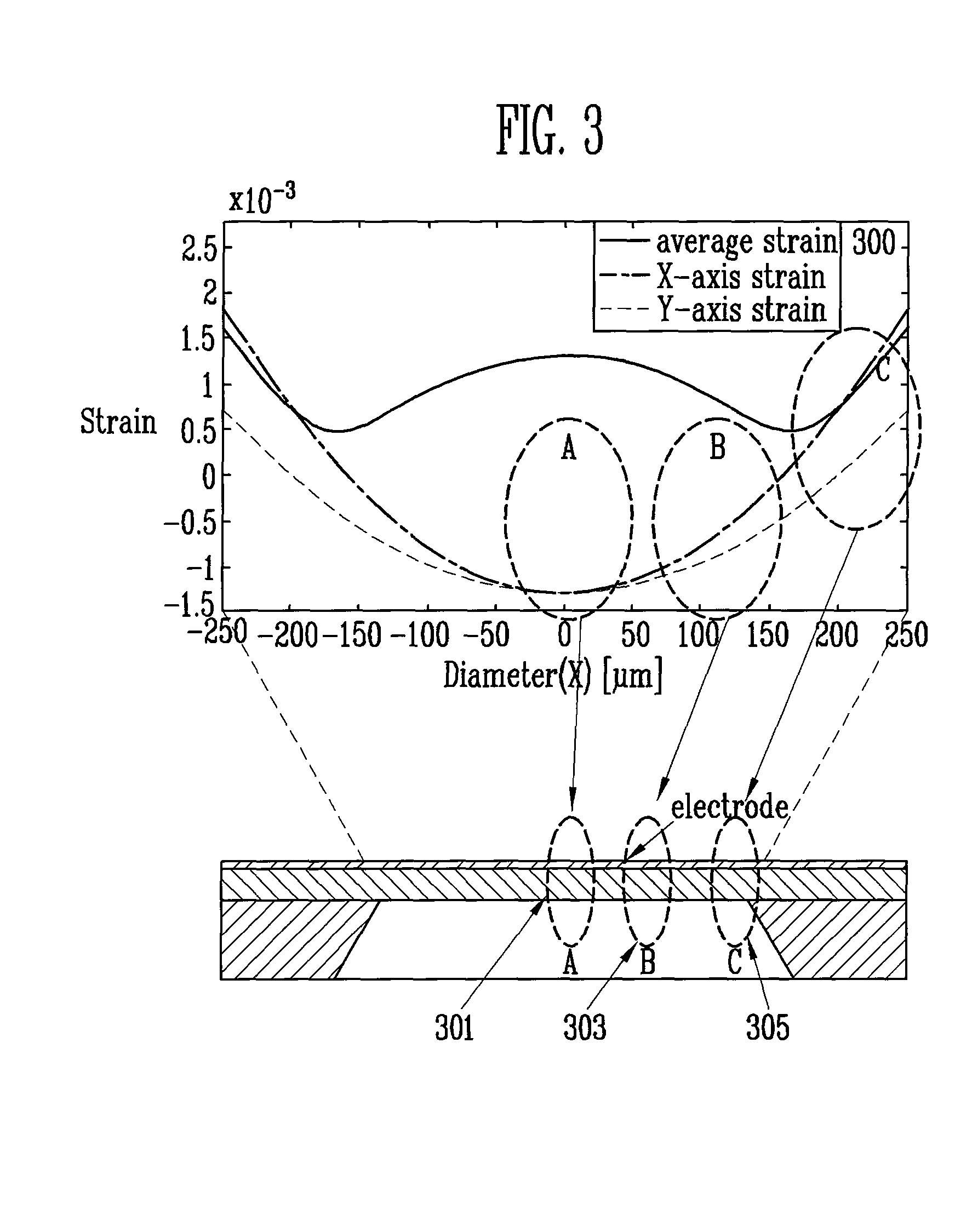
However, the piezoelectric-type acoustic transducer has the problems that the microphone has a relatively low sensitivity due to tensile residual strain in a transducer vibration plate, and the micro-speaker has a low output.

Method used


Image

  • Piezoelectric microphone, speaker, microphone-speaker integrated device and manufacturing method thereof
  • Piezoelectric microphone, speaker, microphone-speaker integrated device and manufacturing method thereof
  • Piezoelectric microphone, speaker, microphone-speaker integrated device and manufacturing method thereof

Examples


third embodiment

[0057]Reference numeral ‘420’ indicates a pattern according to the present invention. Reference numeral ‘420’ shows the existing parallel pattern formed in the next outer circumference in addition to the same pattern as reference numeral ‘410.’ In other words, the patterns branching from the respective electrodes form a parallel secondary pattern.

[0058]Besides the foregoing embodiments, many different patterns are possible. However, according to an embodiment of the present invention, the series mating pattern is formed at only the outer circumference of the microphone. Although the series mating pattern according to an embodiment of the present invention is less than the existing parallel mating pattern, the voltage can be further efficiently output.

[0059]FIGS. 5A and 5B are cross-sectional views of a conventional micro-speaker to be compared with an embodiment of the present invention.

[0060]FIG. 5A is a cross-sectional view of a conventional piezoelectric micro-speaker. Referring ...


PUM


Abstract

A piezoelectric microphone, a speaker, a microphone-speaker integrated device and a manufacturing method thereof are provided. The microphone-speaker integrated device includes a silicon substrate and an insulating layer deposited on the silicon substrate; a piezoelectric plate formed on the insulating layer; and a mating electrode formed on the piezoelectric plate. The mating electrode is patterned with a polarity arrayed in series.

Description

CROSS-REFERENCE TO RELATED APPLICATION[0001]This application claims priority to and the benefit of Korean Patent Application No. 2007-133464, filed Dec. 18, 2007, the disclosure of which is incorporated herein by reference in its entirety.BACKGROUND[0002]1. Field of the Invention[0003]The present invention relates to a piezoelectric microphone, a speaker, a microphone-speaker integrated device, and a manufacturing method thereof, and more particularly, to a microphone with a pattern structure for enhancing efficiency of a piezoelectric microphone having a mating structure, a speaker having a differentially etched piezoelectric plate and a series / parallel mating electrode, a microphone-speaker integrated device, and a manufacturing method thereof.[0004]This work was supported by the IT R&D program of MIC / IITA. [2006-S-006-02, Component Module for Ubiquitous Terminal][0005]2. Discussion of Related Art[0006]Technology for miniaturizing a microphone and a micro-speaker on a silicon wafe...

Claims


Application Information

Patent Timeline
Patent Type & Authority Patents(United States)
IPC IPC(8): H01L21/00H04R25/00
CPCH04R17/025H04R17/10H04R17/00
Inventor KIM, HYE JINLEE, SUNG QLEE, SANG KYUNLEE, JAE WOOPARK, KANG HOKIM, JONG DAE
Owner ELECTRONICS & TELECOMM RES INST
Learn More