
Method for reducing audio noise of display and driving device thereof

a liquid crystal display and audio noise technology, applied in static indicating devices, electrical transducers, instruments, etc., can solve the problems of increased cost of altering circuit design, communication quality deterioration, display quality affected, etc., and achieve the effect of reducing the audio noise of the display substra

Inactive Publication Date: 2012-02-14
NOVATEK MICROELECTRONICS CORP
View PDF13 Cites 1 Cited by
  • Summary
  • Abstract
  • Description
  • Claims
  • Application Information

AI Technical Summary

Benefits of technology

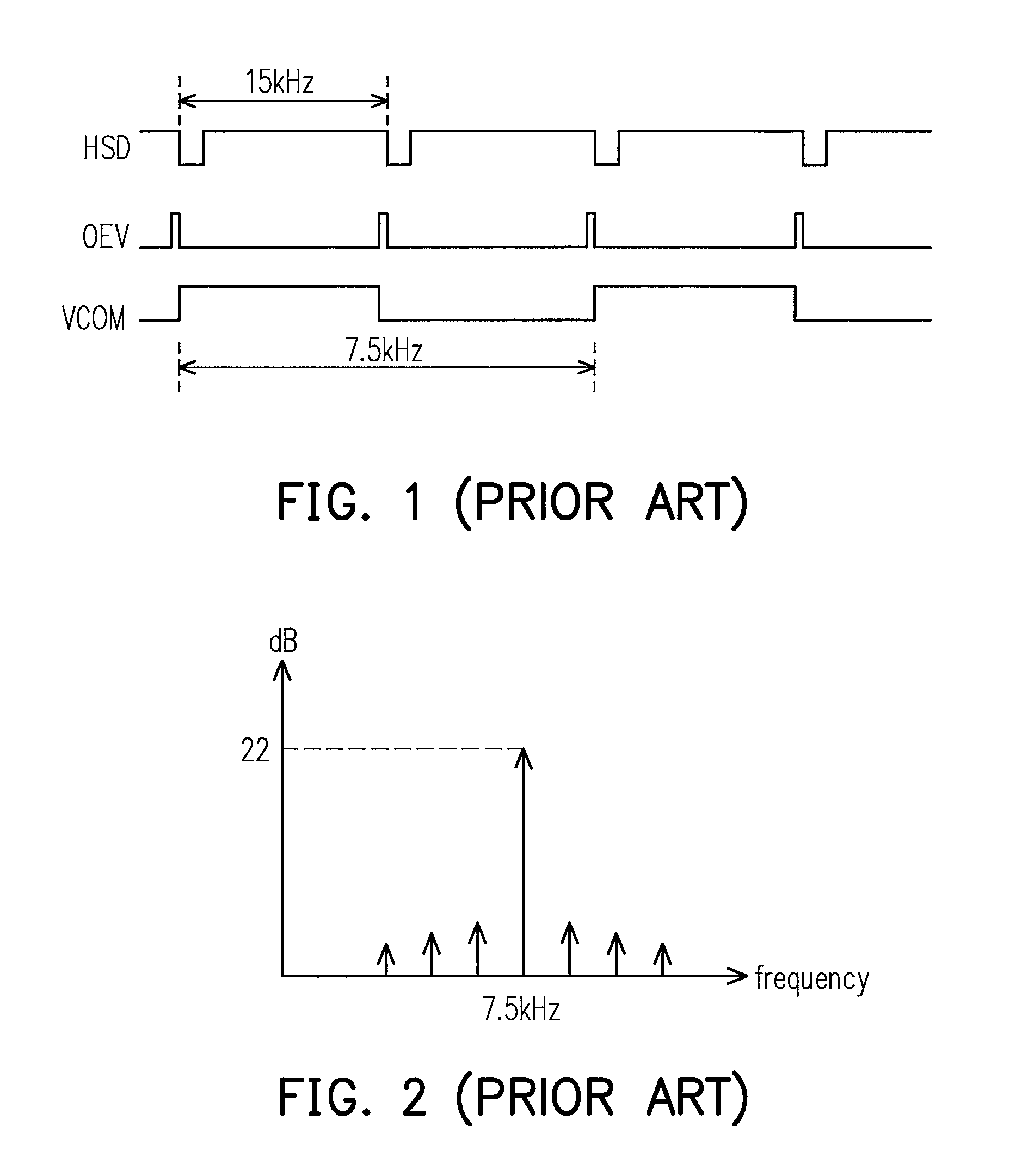
The method significantly reduces the intensity of the 7.5 kHz audio noise, making it inaudible to humans, from 22 dB to 8 dB, without changing the current driving specifications or circuit architecture, thus improving user experience while maintaining display quality and cost-effectiveness.

Problems solved by technology

As for those ordinary small-size mobile devices, for example, mobile phones, the LCD screen is close to the user's ear during the call, so the audio noise may cause troubles when the user is listening to the sounds from the phone, and as a result, the communication quality is deteriorated.
In order to solve the problem, in the conventional art, various methods of changing the scanning time for the scan line and reducing the charging time are used, but as a result, the display quality is affected or the cost for altering the circuit design is increased.
Therefore, how to reduce the influences caused by the audio noise to the user in a more efficient and cost-effective way has become an urgent issue to be solved in this field.

Method used


Image

  • Method for reducing audio noise of display and driving device thereof
  • Method for reducing audio noise of display and driving device thereof
  • Method for reducing audio noise of display and driving device thereof

Examples


Embodiment Construction

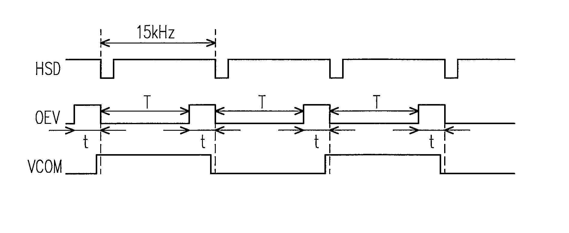
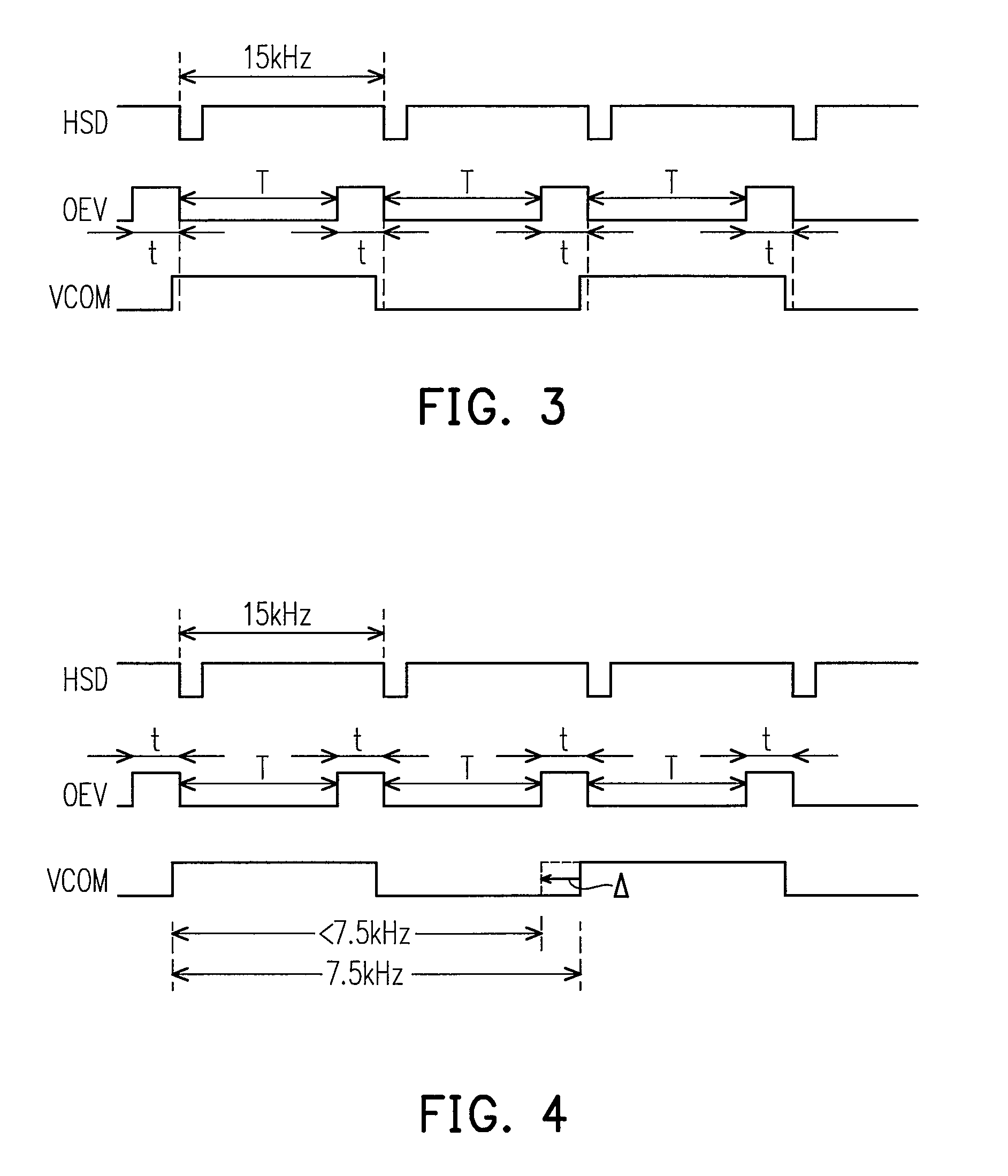
[0030]One of the technical features of the present invention is to use a spread spectrum manner to adjust the frequency of the substrate voltage VCOM, such that the frequency is not fixed at 7.5 kHz, thereby reducing the generation frequency of the frequency 7.5 kHz and reducing the sound intensity. In order to make the frequency of the substrate voltage VCOM be adjustable, the charging time for each scan line is reduced, that is, the width for the output enabling signal (or called reference signal) OEV is increased, so as to adjust the frequency of the substrate voltage VCOM. Then, the content of the present invention is illustrated below through several embodiments.

[0031]FIG. 3 is a schematic view of a concept of reducing audio noise of a display according to an embodiment of the present invention. As known from the above descriptions that, the inversion of the substrate voltage VCOM is performed together with the horizontal synchronization signal HSD when the output enabling sign...


PUM


Abstract

A method for reducing audio noise of a display is provided. A horizontal synchronization signal, a reference signal and a substrate voltage signal are generated. The reference signal has a preset width at high level status. The status transition of the substrate voltage signal is based on each scan line corresponding to the horizontal synchronization signal. In each period of the substrate voltage signal, the status transition of the raising and falling edges is based on the high level status of the reference signal, and the transition timings of the raising edges and the falling edges are advanced or delayed based on a reference value of the high level status of the reference signal.

Description

CROSS-REFERENCE TO RELATED APPLICATION[0001]This application claims the priority benefit of Taiwan application serial no. 96135917, filed Sep. 27, 2007. The entirety of the above-mentioned patent application is hereby incorporated by reference herein and made a part of this specification.BACKGROUND OF THE INVENTION[0002]1. Field of the Invention[0003]The present invention relates to a method for reducing audio noise of a display. More particularly, the present invention relates to a method for reducing audio noise of a liquid crystal display (LCD).[0004]2. Description of Related Art[0005]Generally, an LCD device drives each scan line on a display region through inversion driving manner, thereby inverting the scan line and thus eliminating a problem of DC bias residue on the LCD screen. Practically, voltages with opposite polarities are applied on the same scan line of neighboring frames to drive the liquid crystals. In order to achieve the objective, the driving circuit must invert ...

Claims


Application Information

Patent Timeline
Patent Type & Authority Patents(United States)
IPC IPC(8): G06F3/033G06F3/038G06F3/041G09G3/36G09G5/00H03B29/00H04B15/00
CPCG09G3/3655G09G3/3614G09G2310/08G09G2330/06
Inventor CHENG, FU-YENCHIANG, CHIA-YIN
Owner NOVATEK MICROELECTRONICS CORP
Learn More