
Circuit board device, electronic device provided with the same, and GND connecting method

a technology of circuit board and electronic device, which is applied in the direction of electrical apparatus casing/cabinet/drawer, instrument, and semiconductor/solid-state device details, etc., can solve the problems of increasing the mounting space of the circuit board device, the limitation of the mounting of components, and the increase of the cost, so as to achieve cost reduction, reduce noise interference between the printed board and the effect of efficient us

Inactive Publication Date: 2012-02-14
LENOVO INNOVATIONS LTD HONG KONG
View PDF29 Cites 8 Cited by
  • Summary
  • Abstract
  • Description
  • Claims
  • Application Information

AI Technical Summary

Benefits of technology

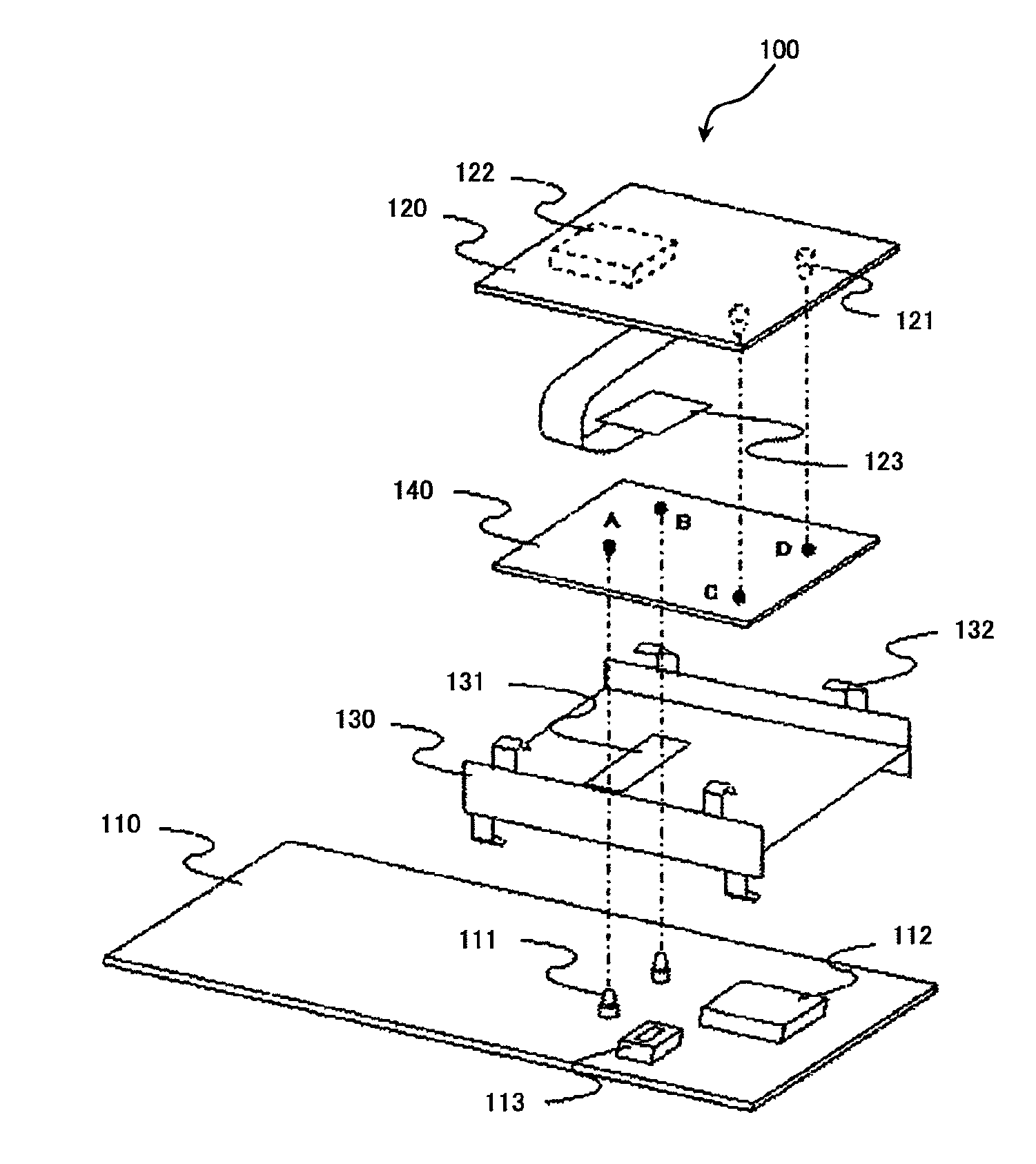
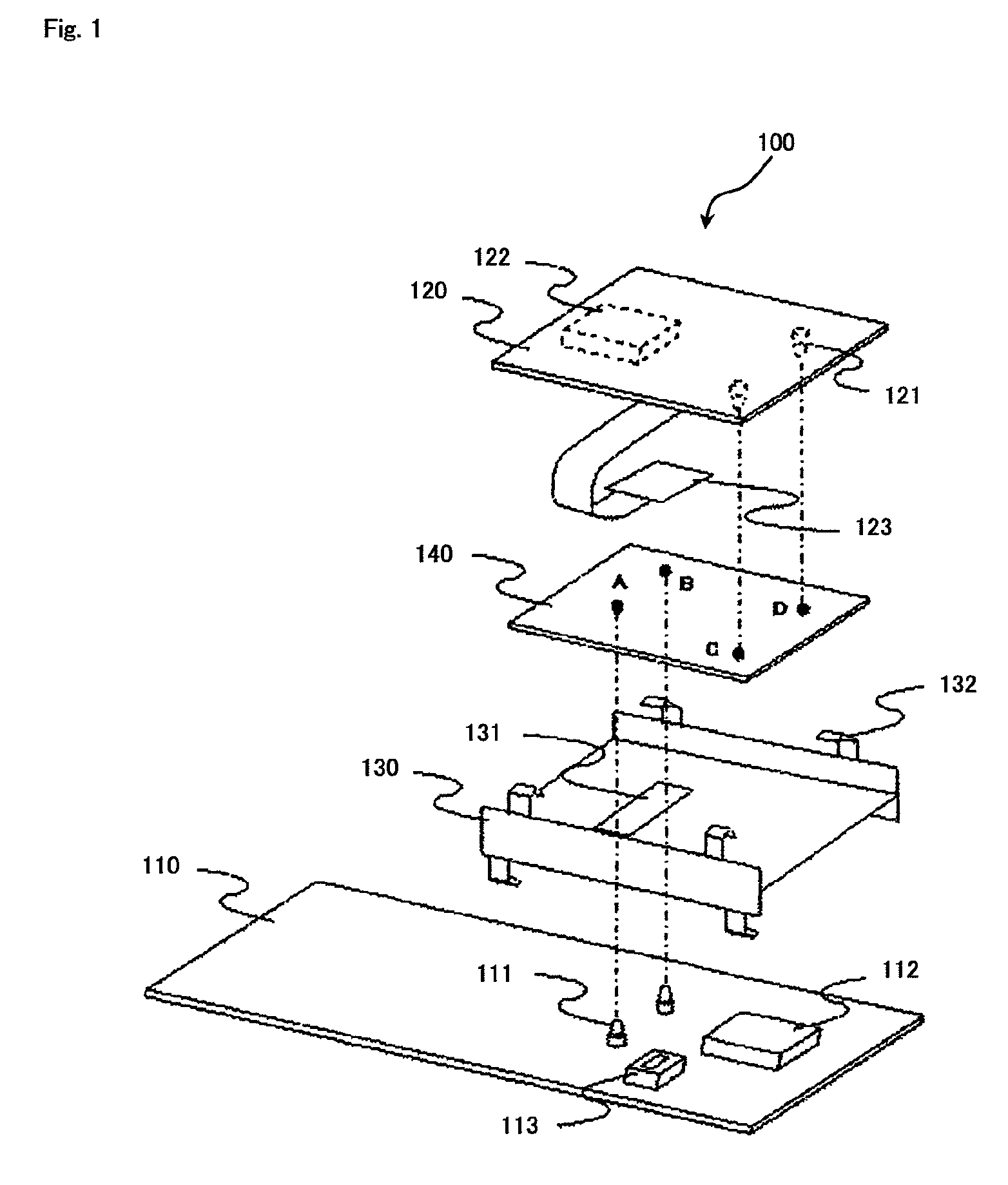
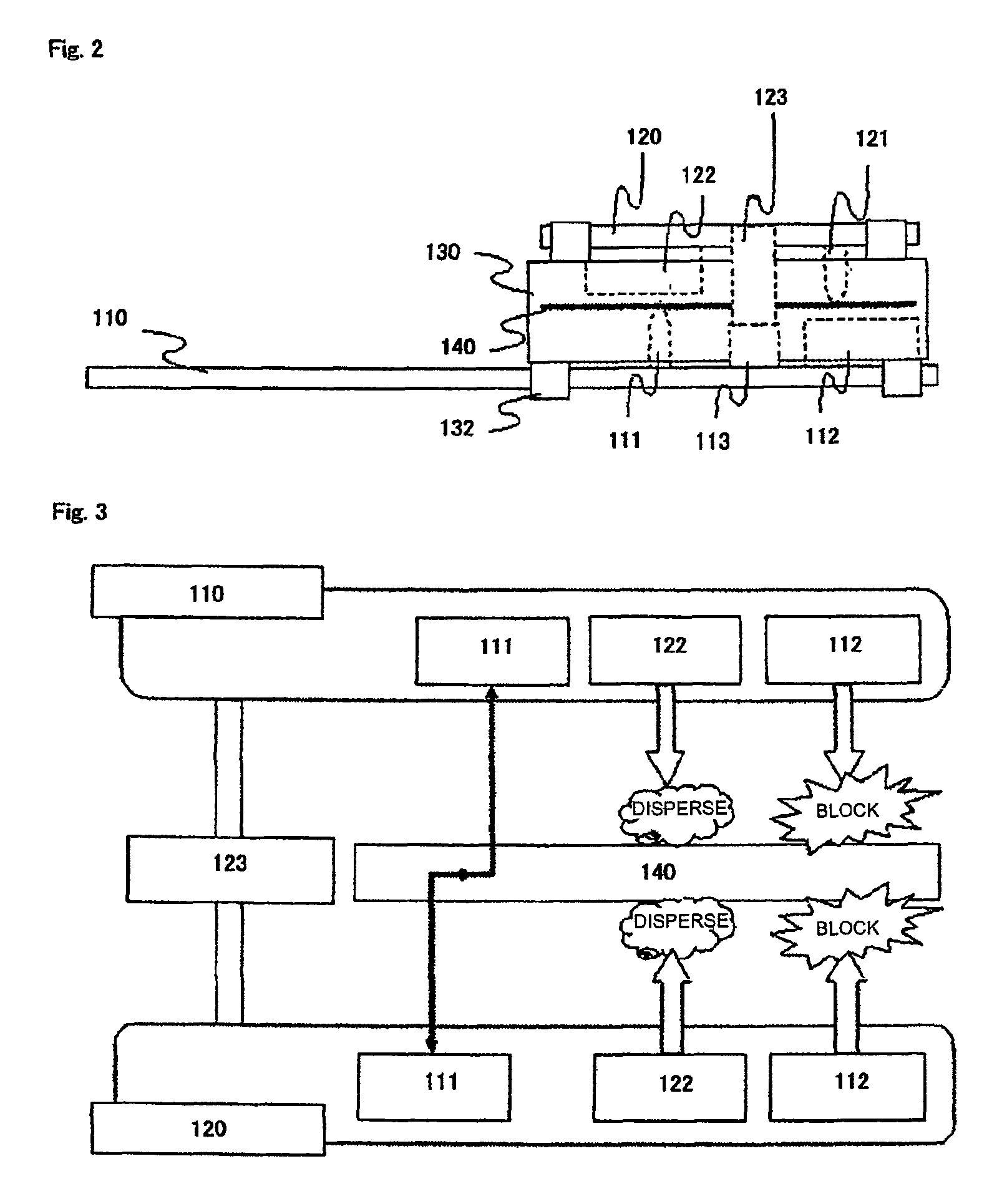
The present invention provides a circuit board device, an electronic device, and a GND connecting method that allow for greater flexibility in the position of the GND connecting terminals on the printed boards. This is achieved by using a metal plate that is inserted between the printed boards and positioned at a distance from the noise generating component and heat generating component. The metal plate acts as a noise shield and heat sink, and the position of the metal plate can be adjusted to overlap with the noise generating component and heat generating component. This eliminates the need for noise interference and heat transfer, and reduces the mounting space and cost of the circuit board device.

Problems solved by technology

Accordingly, there occurs a limitation on the mounting of components.
Consequently, the mounting space of the circuit board device increases, and also the cost increases.

Method used


Image

  • Circuit board device, electronic device provided with the same, and GND connecting method
  • Circuit board device, electronic device provided with the same, and GND connecting method
  • Circuit board device, electronic device provided with the same, and GND connecting method

Examples


Embodiment Construction

[0026]A circuit board device according to an exemplary embodiment includes: a pair of printed boards, each of the pair of printed boards including a mounting surface and a GND connecting terminal provided on the mounting surface, and the pair of printed boards being arranged so that the mounting surfaces of the pair of printed boards face each other; at least one of a noise generating component and a heat generating component, at least one of the noise generating component and the heat generating component being mounted on the mounting surface of at least one of the pair of printed boards; and a metal plate that is provided between the mounting surfaces of the pair of printed boards and that is located at a distance from the noise generating component and / or the heat generating component so as to overlap with the noise generating component and / or the heat generating component, and the metal plate being in contact with the respective GND connecting terminals so that the GND connectin...


PUM

PropertyMeasurementUnit
distanceaaaaaaaaaa
widthaaaaaaaaaa
flexibleaaaaaaaaaa

Abstract

Provided is a circuit board device, wherein degrees of freedom are provided for a GND connecting position among plural printed boards, and noise shield and / or heat sink effects are provided. An electronic device provided with the circuit board device and a GND connecting method are also provided. Circuit board device (100) includes a pair of printed boards (110, 120), noise generating component (112) and / or heat generating component (122), and metal plate (140). Printed boards (110, 120) include mounting surfaces and GND connecting terminals (111, 121) arranged on the respective mounting surfaces, and the mounting surfaces are arranged to face each other. Noise generating component (112) and / or heat generating component (122) is mounted on the mounting surface of at least one of a pair of printed boards (110, 120). Metal plate (140) is arranged between the mounting surfaces of the pair of printed boards (110, 120), and is located at a distance from at least one of noise generating component (112) and heat generating component (122) so as to overlap with the noise generating component and / or the heat generating component. Furthermore, metal plate (140) is in contact with each of GND connecting terminals (111, 121) so that GND connecting terminals (111, 121) are electrically connected to each other.

Description

[0001]This application is the National Phase of PCT / JP2007 / 064186, filed Jul. 18, 2007, which claims priority to Japanese Patent Application No. 2006-198386, filed on Jul. 20, 2006, the entire contents of which are incorporated herein by reference.TECHNICAL FIELD[0002]The present invention relates to a circuit board device with a printed board, an electronic device provided with the circuit board device, and a GND connecting method.BACKGROUND ART[0003]In recent years, because of miniaturization and design consideration, there is a need for more effective mounting methods for circuit board devices that are used in electronic devices such as mobile telephone terminals. In order to meet this need, there is a method for overlapping two printed boards to improve the mounting efficiency. In this case, GNDs of the two printed boards must be connected to each other so that the GNDs of the two printed boards have the same electric potential. As illustrated in FIG. 5, in case the GNDs of firs...

Claims


Application Information

Patent Timeline
Patent Type & Authority Patents(United States)
IPC IPC(8): H05K1/11
CPCH05K1/141H05K9/0049H05K1/0218H05K1/148Y10T29/49126H05K2201/10371H05K2201/2018
Inventor KUBOTA, AKIHITO
Owner LENOVO INNOVATIONS LTD HONG KONG
Learn More