
Computed tomography device and method using circular-pixel position-adaptive interpolation

a computed tomography and position-adaptive interpolation technology, applied in tomography, instruments, nuclear engineering, etc., can solve the problems of loss of lateral resolution, inability to actually project the pixel onto the detector array, and inability to realize the effect of a pixel position projection

Active Publication Date: 2012-02-14
TOSHIBA MEDICAL SYST CORP
View PDF4 Cites 8 Cited by
  • Summary
  • Abstract
  • Description
  • Claims
  • Application Information

AI Technical Summary

Benefits of technology

"The present invention is about a method and apparatus for computed-tomography using a linear path from an x-ray source through a backprojection pixel to determine the position of a channel on an x-ray detector and the width of an interpolation kernel using the distance between the source and the backprojection pixel. This can improve the accuracy and efficiency of computed-tomography."

Problems solved by technology

However, the disadvantage is that actual projection of the pixel onto the detector array is not used to compute V(i,j).
For small pixel sizes the projection of the pixel onto the array is smaller than one channel, causing a loss of lateral resolution.
The disadvantage to this method is that both the channels and pixels must be projected onto a centering axis (typically the y or x axis), which makes processing more complex.

Method used


Image

  • Computed tomography device and method using circular-pixel position-adaptive interpolation
  • Computed tomography device and method using circular-pixel position-adaptive interpolation
  • Computed tomography device and method using circular-pixel position-adaptive interpolation

Examples


first embodiment

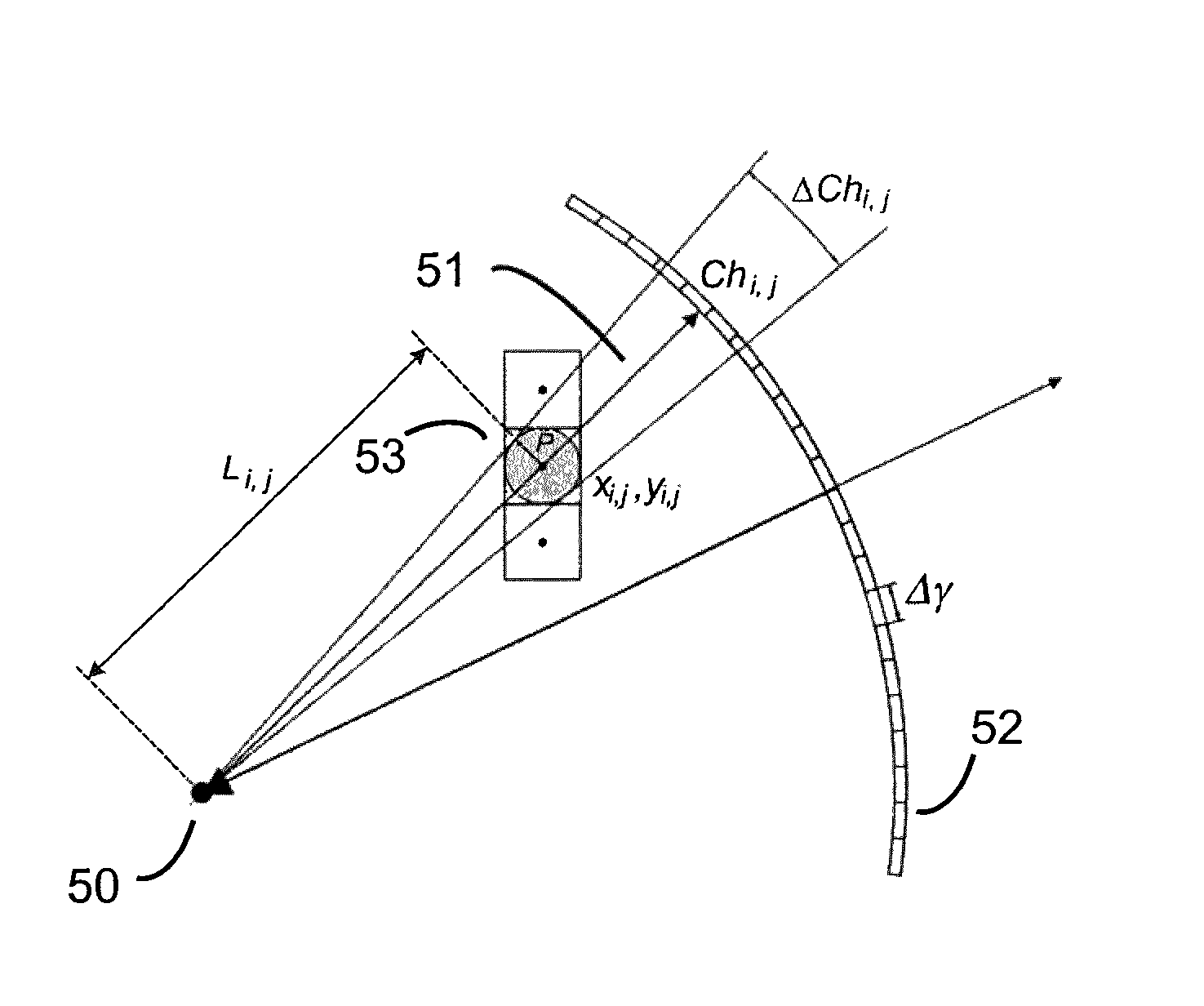
[0039]In the first embodiment, the method is implemented in the channel direction. In an alternate embodiment, the method can be implemented in the segment direction by assuming the voxel is circular in z and calculating the projection of the circle across the segments in the z direction, as shown in FIG. 10. Q is the pixel radius in z and is equal to the reconstruction slice spacing (though in other embodiments it can be calculated differently). FIGS. 10A-E show results for FOVs of 500, 400, 320, 240 and 180, respectively. The solid lines represent the present invention and the dashed lines show, for comparison, distance driven backprojection.

[0040]The floating point segment position is determined exactly the same as it is for the pixel-driven method:

[0041]zseg=D·zpL(16)

where zseg is the distance from the then center of the detector to the backprojection segment location, D is the source to detector distance and is zp is the z distance of the reconstruction pixel from the source-de...

third embodiment

[0046]In a third embodiment, the method can be implemented for both the channel and segment directions at the same time. This is the 3-D case, where the circular pixel is now a spherical voxel with radius S. Equations (6-15) are used to calculate channel direction projection with P=S and equations (16-22) for segment direction, with Q=S. This embodiment can be used for full cone-beam detectors.

[0047]The invention may also be embodied in the form a computer-readable medium containing a stored program to cause a computer to carry out the various operations and functions described above.


PUM


Abstract

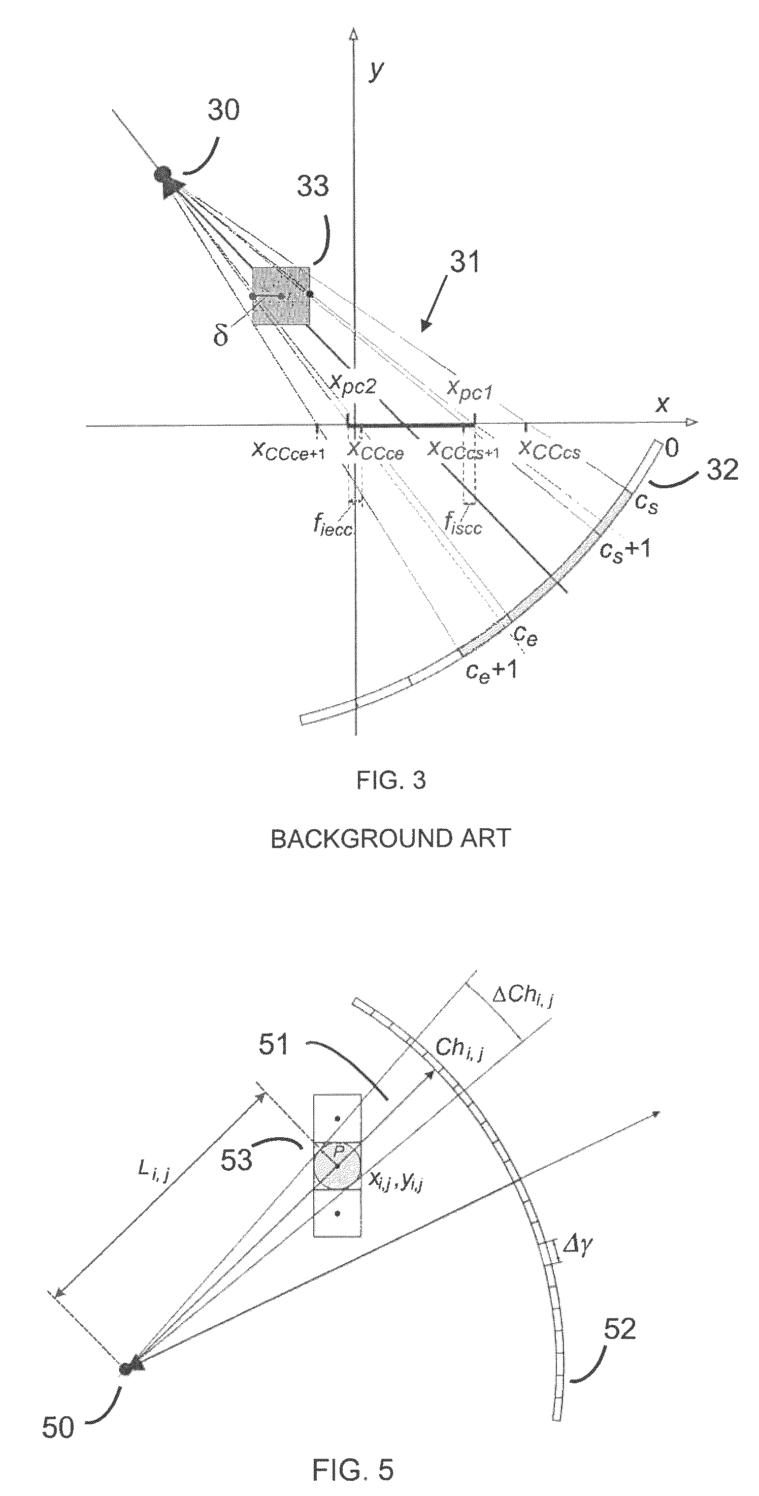
A method of computed-tomography and a computed-tomography apparatus where a interpolation kernel width is adaptively determined as a function of the distance from the x-ray source to the reconstruction pixel. The width of the kernel is the projection of the reconstruction pixel on the detector. The method can be implemented in the channel direction. The method can also be implemented in the segment direction, or in the channel and segment directions at the same time. Backprojection is performed using the adaptive kernel width and may by used with helical and circular scanning, and with cone-beam or fan beam x-ray CT.

Description

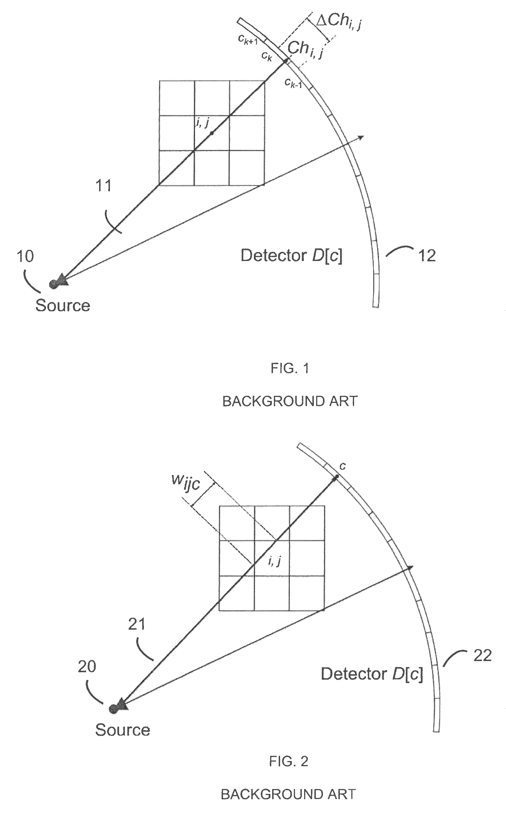
BACKGROUND OF THE INVENTION[0001]1. Field of the Invention[0002]The present invention relates to helical and circular x-ray computed tomographic (CT) imaging, and in particular to CT imaging with adaptive interpolation.[0003]2. Discussion of the Background[0004]There are several methods of backprojection. A common method is pixel-driven backprojection illustrated in FIG. 1. A ray 11 is drawn from the source 10 through the center of the reconstruction pixel at (i,j) to the detector array 12. Ray 11 intersects detector 12 at floating point channel index Chi,j on channel ck. The value assigned to the pixel is a linear interpolation of the values of the detector the ray intersects and the adjacent elements:V(i,j)=wk−1·D(ck−1)+wk·D(ck)+wk+1·D(ck+1)  (1)where ck is the channel of intersection and wk−1+wk+wk+1=1. For typical linear interpolation, the interpolation kernel width ΔCh is fixed at one channel and only two detector elements are used (either wk−1 or wk+1 is zero). A nearest neigh...

Claims


Application Information

Patent Timeline
Patent Type & Authority Patents(United States)
IPC IPC(8): A61B6/03
CPCG06T11/005A61B6/032
Inventor HEIN, ILMARZAMYATIN, ALEKSANDR
Owner TOSHIBA MEDICAL SYST CORP
Learn More