Apparatus for controlling power generated by on-vehicle generator on the basis of internal status of on-vehicle battery

a technology of on-vehicle generator and battery, which is applied in the direction of instruments, heat measurement, transportation and packaging, etc., can solve the problems of inability to recognize the signals of sensors properly by the controller, inductive noise, and the like, and achieves low resistance, easy detection of bus bar temperature, and improved thermal coupling characteristics

Active Publication Date: 2012-02-21
DENSO CORP
View PDF11 Cites 2 Cited by
  • Summary
  • Abstract
  • Description
  • Claims
  • Application Information

AI Technical Summary

Benefits of technology

[0011]An object of the present invention is to provide an apparatus that is able to prevent various difficulties, such as a malfunction due to noise and improper wiring, caused in association with the fact that sensors and circuits boards are connected using signal wirings, thus improving the reliability of the apparatus.
[0012]To achieve above-described object, an apparatus for controlling power generation of a generator mounted on a vehicle, the generator charging an on-vehicle battery is provided. The apparatus comprises a detecting device that detects information indicating an internal status of the battery that includes temperature of the battery, a power supply circuit that supplies power to the detecting device, a calculator (i.e., an arithmetic circuit) for calculating the internal status of the battery using the information detected by the detecting device, a circuit board on which the calculator, the power supply circuit, and the detecting circuit are mounted and a controller that controls the power generation of the generator based on the internal status of the battery. The temperature sensing element is arranged on a bus bar that is electrically connected to a negative terminal of the battery, and the bus bar and the temperature sensing element are coupled thermally to each other. Therefore, since no external wiring is required to connect the board and the sensor (i.e., the temperature sensing element), unwanted noise propagating through the wiring can be removed so that malfunction of the apparatus caused by the noise disappears and also, decreasing reliability caused by the vibration stress in the vehicle can be prevented.
[0013]Furthermore, the connection between the circuit board and the temperature sensing element can be completed in the same manufacturing step as connecting the arithmetic circuitry and the power supply circuit. Thus, the assembly cost of the vehicle can be reduced along with the work load. Also, since the wiring is in the circuit board, the vehicle's reliability can be improved by avoiding improper wiring between devices.

Problems solved by technology

Accordingly, the above-described related art has a drawback, as described below.
In vehicles, inductive noise occurs while the ignition system, which is in operation, causes electrical noise which may partly propagate to signal wirings which connect various sensors and electrical circuit boards.
Accordingly, if such a case occurs, signals from the sensors cannot be recognized properly by a controller.
Moreover, when the vehicle is running, there is a concern that the signal wirings may be cut or disconnected due to vibration stress coming from the road or the on-vehicle engine.
There are additional problems concerning the above wiring connection manner.
First, since the temperature sensor is arranged apart from the circuit board, mounting the sensor to the vehicle needs much work, thus raising assembling cost as a whole.
Another problem is that the number of signal wirings increases, whereby wiring errors are more likely to occur.

Method used


Image

  • Apparatus for controlling power generated by on-vehicle generator on the basis of internal status of on-vehicle battery
  • Apparatus for controlling power generated by on-vehicle generator on the basis of internal status of on-vehicle battery
  • Apparatus for controlling power generated by on-vehicle generator on the basis of internal status of on-vehicle battery

Examples


Embodiment Construction

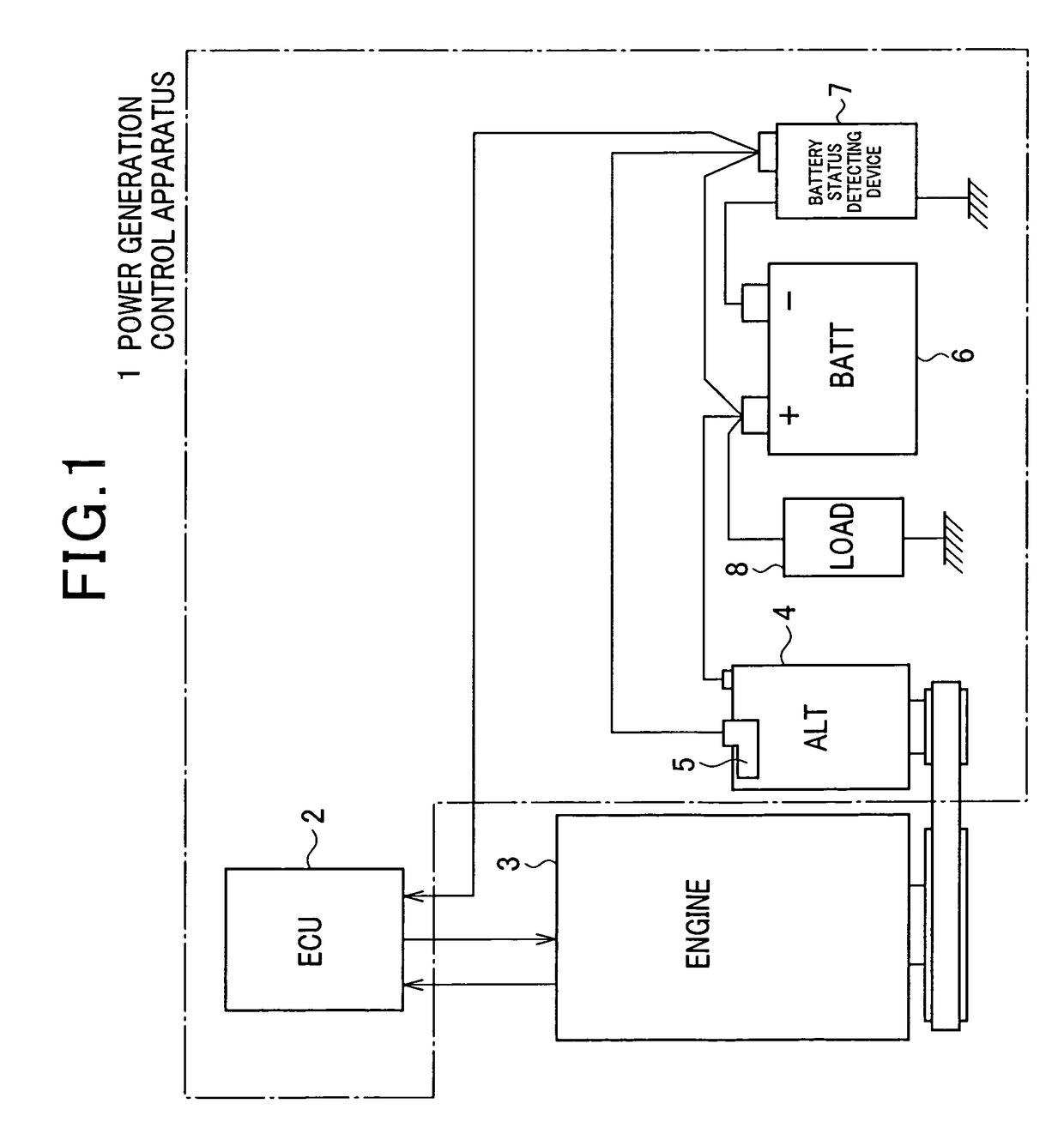
[0024]An exemplary embodiment of a power generation control apparatus of the present invention is below described with reference to the attached drawings. FIG. 1 illustrates a configuration of a power generation control apparatus 1 according to an embodiment. As shown in FIG. 1, the power generation control apparatus 1 includes an ECU 2 (Electronic Control Unit 2), an engine 3, a vehicle generator (ALT) 4, a battery (BATT) 6, and a battery status detecting device 7.

[0025]The ECU 2 is an electronic control unit that controls an output of the engine 3 as an external controller. The vehicle generator 4 is rotated by the engine via a belt, and generates power. The power is provided to the battery 6 as a charging power and to various electrical loads (LOAD) 8. The generator (ALT) 4 includes a generation controller 5 that controls the output of the generator by adjusting the exciting current. The battery status detecting device 7 is arranged close to the battery 6 to detect the internal s...


PUM

PropertyMeasurementUnit
power generationaaaaaaaaaa
temperatureaaaaaaaaaa
thicknessaaaaaaaaaa

Abstract

An apparatus for controlling power generation of a generator mounted on a vehicle, the generator charging a on-vehicle battery, comprising a detecting device that detects information indicating the internal status of the battery that includes temperature of the battery, a power supply circuit that supplies power to the detecting device, a calculator for calculating the internal status of the battery using the information detected by the detecting device, a circuit board on which the calculator, the power supply circuit, and the detecting circuit are mounted and a controller that controls the power generation of the generator based on the internal status of the battery. The temperature sensing element is arranged on a bus bar that is electrically connected to the negative terminal of the battery, and the bus bar and the temperature sensing element are coupled thermally to each other.

Description

CROSS-REFERENCE TO RELATED APPLICATION[0001]This application is related to Japanese Patent Application NO. 2007-209359 filed on Aug. 10, 2007, the contents of which are hereby incorporated by reference.BACKGROUND OF THE INVENTION[0002]1. Field of the Invention[0003]The present invention relates to a power generation control apparatus for vehicles and in particular, to an apparatus for controlling power generated by an on-vehicle generator based on the internal status of the battery mounted on vehicles such as cars and trucks.[0004]2. Description of the Related Art[0005]In recent years, a vehicle is usually provided with an apparatus for controlling power generated by an alternator (i.e., a vehicular AC generator). Some of these control apparatuses need information indicative of how the battery degrades. One of such control apparatuses is disclosed by, for example, Japanese Patent Laid-Open Publication Number JP2006-10601. The control apparatus disclosed by this patent publication co...

Claims


Application Information

Patent Timeline
Patent Type & Authority Patents(United States)
IPC IPC(8): H02J7/04H02J7/16B60R16/02B60R16/04G01K1/14G01R31/36
CPCG01K1/14H02J7/1407G01R31/3696G01R1/203G01R31/364
Inventor ASADA, TADATOSHI
Owner DENSO CORP
Why Eureka
Try Eureka