Reflective optical system, tracking system and holographic projection system and method

a tracking system and optical system technology, applied in the field of reflection optical system, can solve problems such as inability to use a static mirror, and achieve the effect of computing load

Active Publication Date: 2012-02-21
SEEREAL TECHNOLOGIES
View PDF9 Cites 73 Cited by
  • Summary
  • Abstract
  • Description
  • Claims
  • Application Information

AI Technical Summary

Benefits of technology

[0028]A tracking system according to this invention preferably comprises a position control means for controlling the position of the pupil or of an identical image of the pupil in the entry-side focal point of the reflective optical system. It is also possible to change the position of the pupil only virtually, e.g. using mirrors etc. When changing the position of the

Problems solved by technology

This is not possible

Method used


Image

  • Reflective optical system, tracking system and holographic projection system and method
  • Reflective optical system, tracking system and holographic projection system and method
  • Reflective optical system, tracking system and holographic projection system and method

Examples


first embodiment

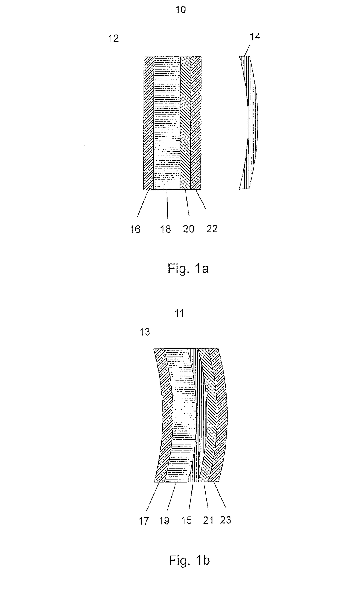
[0035]FIG. 1a is a top view showing the design of a deflection element 12 and a reflection element 14 of a reflective optical system 10 according to the present invention, with an optically addressable spatial light modulator (OASLM) with a diffractive structure as the deflection element 12 and a static basic mirror as the reflection element 14. The basic mirror 14 can for example be a metallic mirror with a reflecting surface.

[0036]The OASLM 12, which is disposed in front of the basic mirror 14, seen from the focal points, comprises a first glass plate 16 with a transparent electrode, an LC layer 18 which forms the diffractive structure of the OASLM 12 and which has LC molecules, a transparent photosensitive semiconductor layer 20 and a second glass plate 22 as substrate. According to this embodiment, the photosensitive semiconductor layer 20 is transparent, so that reconstruction light waves can pass on to the reflection element 14 disposed behind. Generally, the reconstruction li...

second embodiment

[0037]FIG. 1b is a top view showing the design of a deflection element 13 and a reflection element 15 of a reflective optical system 11 according to the present invention, with an optically addressable spatial light modulator (OASLM) with a diffractive structure as deflection element 13, where the reflection element 15 is integrated into said OASLM in the form of a reflective layer.

[0038]In the second embodiment, the OASLM 13 comprises a glass plate 17 with a transparent electrode, an LC layer 19, which forms the diffractive structure of the OASLM 13 and which has LC molecules, a photosensitive semiconductor layer 21 and a glass plate 23 as substrate. The reflection element 15 is integrated between the LC layer 19 and the semiconductor layer 21 in this second embodiment.

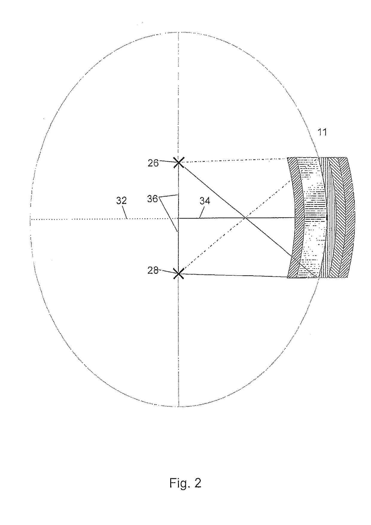
[0039]Referring to FIG. 2, the geometric relations in a reflective optical system according to this invention will now be explained for the arrangement shown in FIG. 1b (these may be applied also to the arrangement s...


PUM


Abstract

The invention relates to an optical reflection system with a reflection element for reflecting reconstruction light waves, an entry-side focal point, from which the reconstruction light waves come when they hit the reflection element, and an exit-side focal point, to which the reconstruction light waves propagate after being reflected from the reflection element. The invention further relates to a tracking system and a holographic projection system with such optical reflection system, and a corresponding holographic projection method. In order to achieve with such an optical reflection system an aberration correction and a tracking of the visibility region and a reconstruction larger than with prior art devices, the optical reflection system according to this invention comprises a deflection element with optically controllable deflection properties and a deflection control means for optically controlling the deflection properties of the deflection element which controls the position of at least the exit-side focal point of the optical reflection system.

Description

CROSS REFERENCE TO RELATED APPLICATIONS[0001]This application claims the priority of PCT / EP2007 / 051094, filed on Feb. 6, 2007, which claims priority to DE 10 2006 024092.8, filed May 12, 2006, the entire contents of which are hereby incorporated in total by reference.FIELD OF THE INVENTION[0002]The invention relates to a reflective optical system with a reflection element for reflecting reconstruction light waves, an entry-side focal point, from which the reconstruction light waves come when they hit the reflection element, and an exit-side focal point, to which the reconstruction light waves reflected by the reflection element propagate. The invention further relates to a tracking system and a holographic projection system with such a reflective optical system, and a corresponding holographic projection method.BACKGROUND OF THE INVENTION[0003]Holographic projection devices modulate sufficiently coherent light by means of spatial light modulator means. Due to interference of the lig...

Claims


Application Information

Patent Timeline
IPC IPC(8): G02B5/32G03H1/26
CPCG02B5/32G02B27/0037G02B27/0068G02B27/225G02F1/1354G03H1/22G03H1/2205G02B27/4211G02B27/4294G02F2203/01G02F2203/12G02F2203/50G03H1/2294G02B26/08G03H1/08G02B27/18G02F1/135
Inventor SCHWERDTNER, ARMIN
Owner SEEREAL TECHNOLOGIES
Why Eureka
Try Eureka