Inner-tube assembly for bicycle wheel

a technology of inner tubes and bicycle wheels, which is applied in the field of inner tubes for bicycle wheels, can solve the problems of increasing the frequency of flat tires, damage to the inner tubes, and the pump head, and achieves the effects of facilitating the attachment of a fastener, reducing the occurrence of holes, and facilitating the attachment of a pump head

Active Publication Date: 2012-02-28
SPECIALIZED BICYCLE COMPONENTS INC
View PDF32 Cites 7 Cited by
  • Summary
  • Abstract
  • Description
  • Claims
  • Application Information

AI Technical Summary

Benefits of technology

[0009]The present invention provides an inner-tube assembly, including a valve and an inner-tube, that is designed to decrease the occurrence of holes in the inner-tube in the area around the valve assembly. In one aspect, the valve is designed to have a valve housing including a lower portion with a part that is threaded and an upper portion with a part that is substantially unthreaded. The threading on the lower portion facilitates attachment of a fastener to secure the valve relative to the bicycle rim. The absence of threading from the part of the upper portion of the valve housing facilitates attachment of a pump head to a location of the valve housing that is free of threads, thus reducing the likelihood of damage to the pump head, and further reducing the force required to remove the pump head from the valve housing. In one embodiment, the valve housing can be provided with a threaded tip that facilitates attachment of a valve cap. Preferably the valve tip has a diameter smaller than the non-threaded portion of the valve housing so that the threads on the tip are not significantly engaged by a pump head during the inflating process.

Problems solved by technology

The interaction between the pump head and the external threads has been found to damage the pump head.
In addition, removal of the pump head from the external threads can require a significant force, which can cause damage to the pump head, the inner-tube, or both.
These reduced wall thicknesses have resulted in an increased frequency of flat tires caused by air leaking through holes in the inner-tube.

Method used


Image

  • Inner-tube assembly for bicycle wheel
  • Inner-tube assembly for bicycle wheel
  • Inner-tube assembly for bicycle wheel

Examples


Embodiment Construction

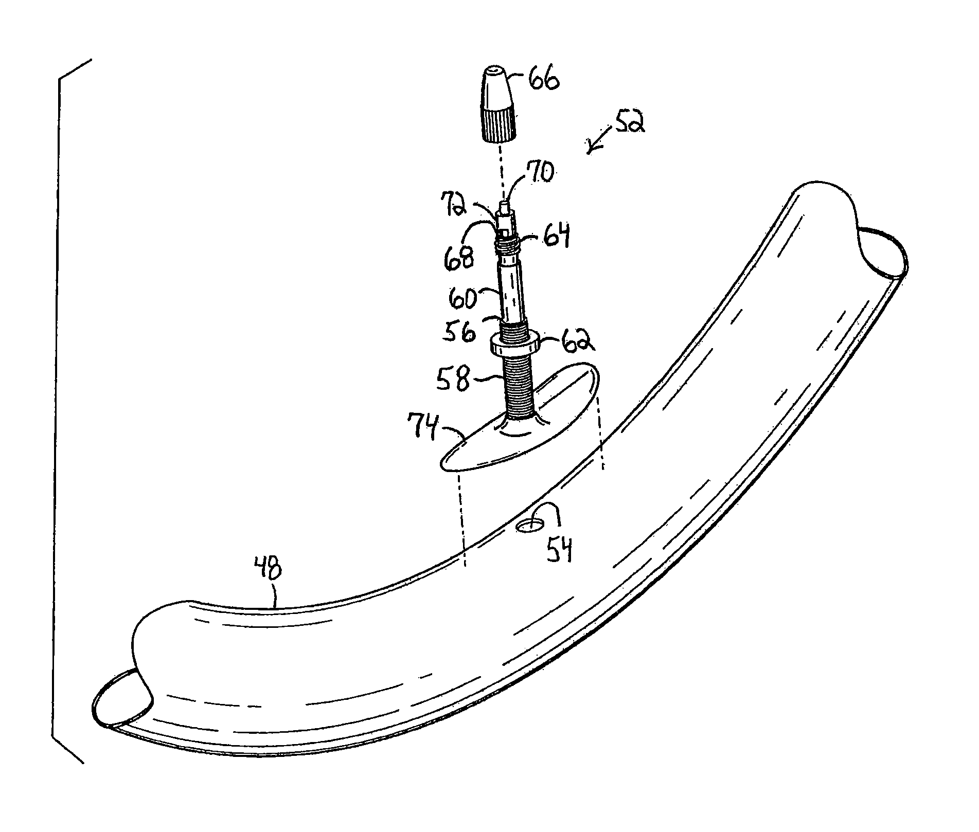
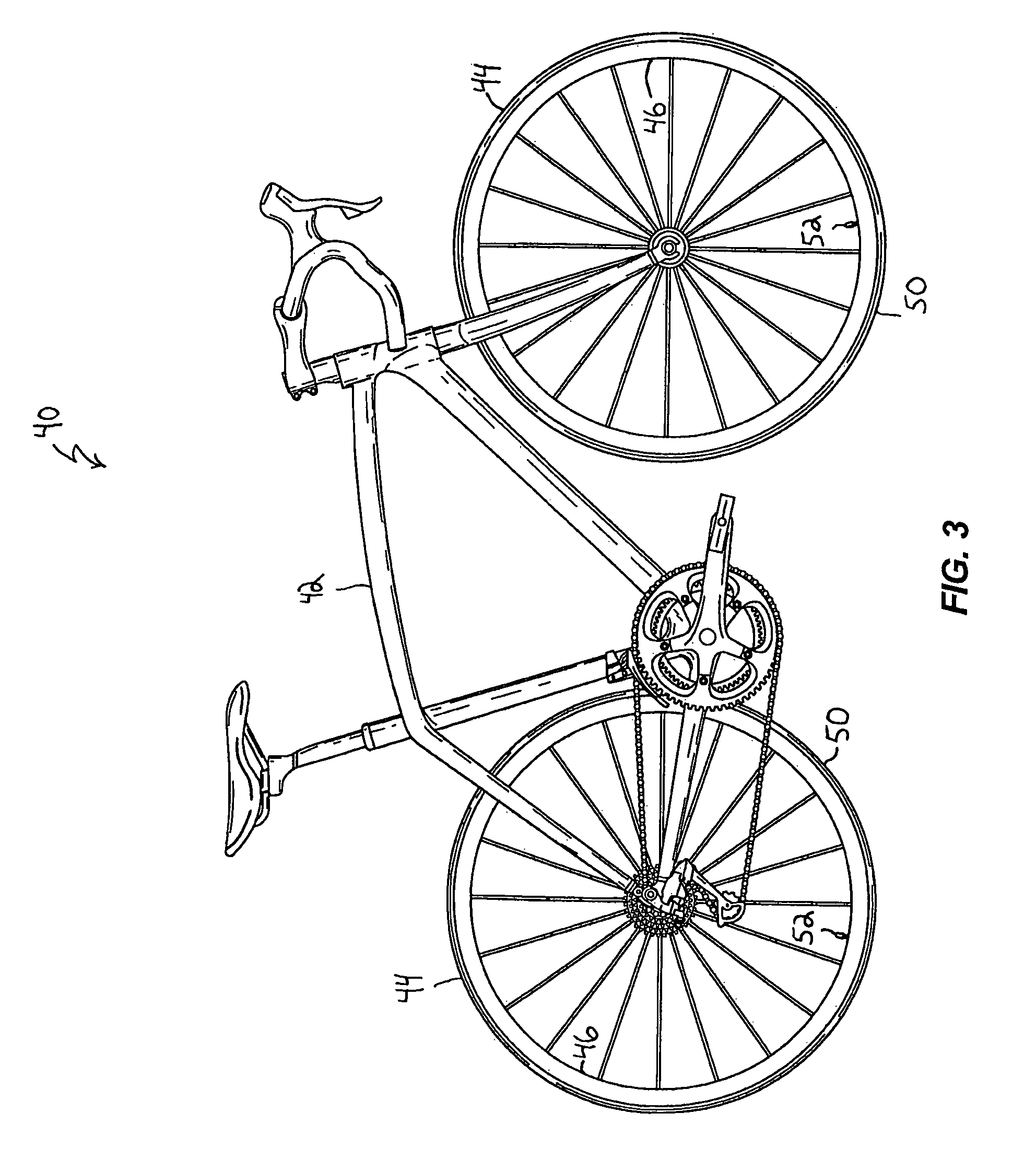
[0018]The bicycle 40 illustrated in FIG. 3 includes a frame 42 and two wheels 44, as is generally known in the art. As shown in FIG. 4, each of the wheels 44 includes a rim 46, an inner-tube 48 and a tire 50. The inner-tube 48 includes a valve assembly 52 that is positioned through a hole 53 in the rim 46 to facilitate access for inflation of the tire 50.

[0019]Referring to FIGS. 5 and 7, the valve assembly 52 includes a valve housing 56. In one embodiment, the valve housing 56 has an overall length L1 of about 50 millimeters. In other embodiments, the valve housing can have overall lengths L1 between about 30 millimeters to about 65 millimeters. The overall lengths L1 of the valve housing 56 can differ to correspond with the depth of the rim 46.

[0020]The valve housing 56 includes a threaded lower portion 58 and an unthreaded upper portion 60. As illustrated in FIGS. 5 and 7, the upper portion 60 has an external diameter that is smaller than an external diameter of the lower portion ...


PUM


Abstract

An inner-tube assembly that includes an inner-tube and a valve assembly. The valve assembly is configured to facilitate the inflation of the inner-tube, and the valve assembly includes a valve core and a valve housing. The valve housing has a lower portion coupled to the inner-tube and an opposite upper portion. At least part of an exterior surface of the lower portion is threaded and at least part of an exterior surface of the upper portion is unthreaded. In another aspect, the inner-tube assembly includes the inner-tube and a valve assembly. An attachment member couples the valve assembly to the inner-tube. The attachment member has a length and a width defining an aspect ratio of width / length, and the aspect ratio is less than about 0.50.

Description

CROSS-REFERENCE TO RELATED APPLICATIONS[0001]This application claims the benefit of U.S. Provisional Patent Application No. 60 / 728,688, filed Oct. 19, 2005, the entire contents of which are hereby incorporated by reference.FIELD OF THE INVENTION[0002]The present invention relates generally to the field of bicycles and, more specifically, to inner-tube assemblies for bicycle wheels.BACKGROUND OF THE INVENTION[0003]Modern bicycles have pneumatic tires that provide good traction and reduce the transmission of vibrations caused by a rough surface. An inner-tube is commonly used to contain pressurized air within the tire. A valve assembly is coupled to the inner-tube to provide a mechanism for inflating the inner-tube. The valve assembly is commonly positioned through a hole in a bicycle rim so that the free end of the valve assembly is available to receive a pump head for inflating the tire.[0004]One common type of bicycle valve is called a Schrader valve, as illustrated in FIG. 1. A Sc...

Claims


Application Information

Patent Timeline
Patent Type & Authority Patents(United States)
IPC IPC(8): B60C29/04
CPCB60C5/04B60C29/04Y10T152/10495Y10S152/11B60C2200/12
Inventor SINYARD, MICHAEL W.REGINA, CHANCE
Owner SPECIALIZED BICYCLE COMPONENTS INC
Why Eureka
Try Eureka