Shaft structure of retractable outer mirror

a shaft structure and mirror technology, applied in the direction of mirrors, mountings, instruments, etc., can solve the problems of difficult use of the shaft in one place, advantageous to a reduction in manufacturing cost, etc., and achieve the effect of increasing bending rigidity, stably arranged, and increasing bending rigidity

Inactive Publication Date: 2012-02-28
MURAKAMI CORP
View PDF16 Cites 8 Cited by
  • Summary
  • Abstract
  • Description
  • Claims
  • Application Information

AI Technical Summary

Benefits of technology

[0014]The shaft structure of a retractable outer mirror has a configuration in which the second member having a clutch part is fitted in with the first member from above. The configuration eliminates a need of modifying the first member even if the second member is modified according to a configuration of a clutch mechanism or the like. This enables a shared use of components necessary for manufacturing the first member.
[0015]At least one of the first member and the second member is preferably, but not necessarily, made of a deep-drawn steel sheet. With the configuration, at least one of the first member and the second member is formed from steel sheet, thus ensuring necessary rigidity. Further, the steel-made first member and / or second member each have a hollow center, thus allowing a reduction in weight. Work hardening generated by the deep-drawing can further increase rigidity of the shaft.
[0017]A thickness of the base section of the first member is preferably, but not necessarily, larger than a thickness of the shaft section. The configuration enables the shaft to increase bending rigidity.
[0018]A bottom surface of the first member is preferably, but not necessarily, flush with a bottom surface of the second member. The configuration enables the shaft to be stably arranged without rattling and to increase bending rigidity.
[0019]Preferably, but not necessarily, the catch part includes a guide groove extending from a top end toward a base end of the shaft section; and a catch groove extending from the guide groove toward a circumferential direction of the shaft section. The catch member includes: an insert hole into which the shaft section is inserted; and a protruding part protruding from an inner circumferential surface of the insert hole toward the center of the insert hole. The protruding part of the catch member is inserted into the guide groove of the catch part. The catch member is rotated in a circumferential direction of the shaft section while the elastic member is pressed down. The protruding part is caught at the catch groove with energizing force of the elastic member. The configuration enables the catch member to be easily caught by the shaft.

Problems solved by technology

This makes it difficult for the shaft used in one place to be used in another, which is not advantageous to a reduction in cost of manufacturing.

Method used


Image

  • Shaft structure of retractable outer mirror
  • Shaft structure of retractable outer mirror
  • Shaft structure of retractable outer mirror

Examples


first embodiment

[0037]Next are described in detail embodiments of the present invention with reference to the attached drawings. Note that an up and down direction referred to in the following description is based on an up and down direction of an auto body S.

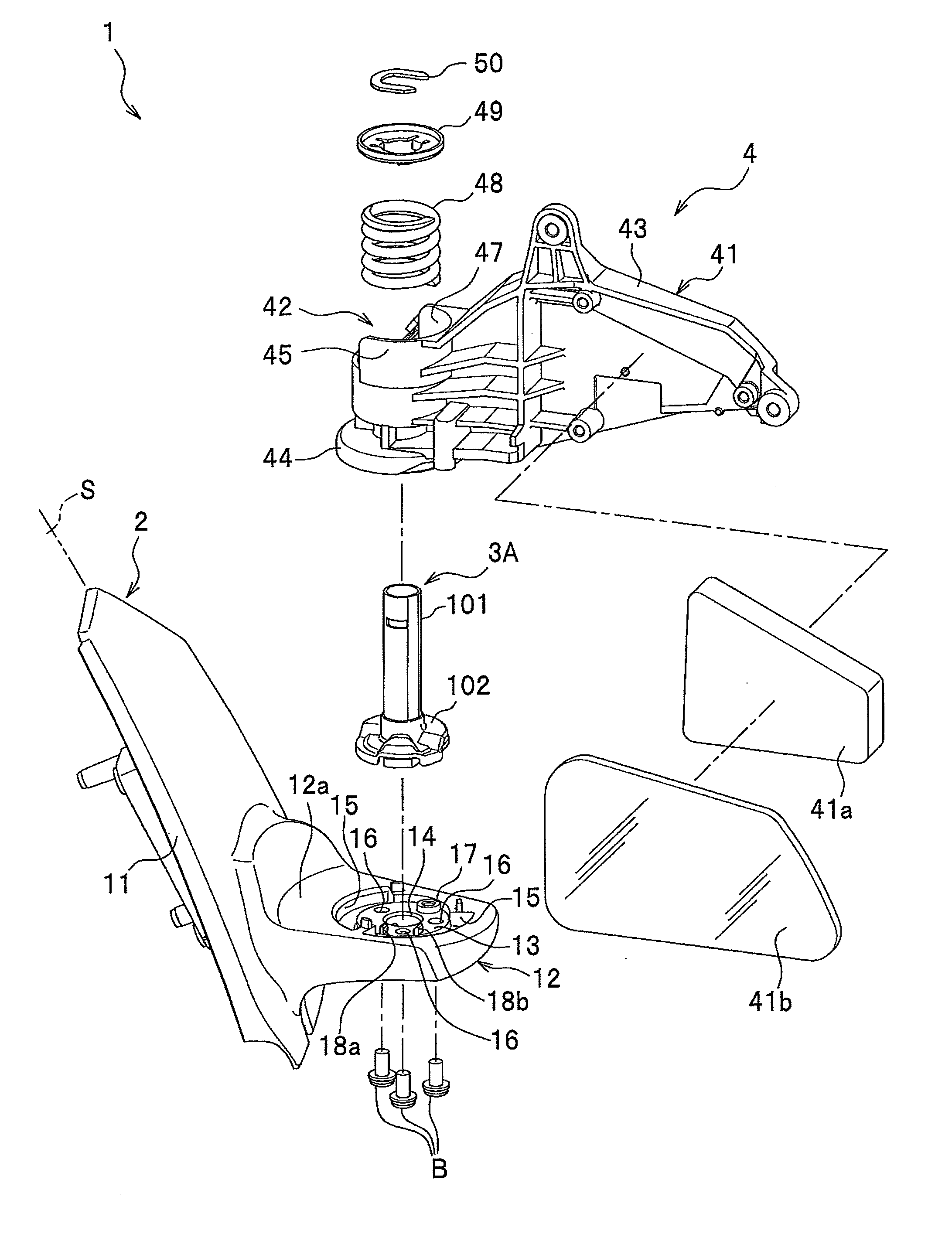
[0038]As shown in FIG. 1, a retractable outer mirror (which may also be simply referred to as an outer mirror) 1 according to the first embodiment is a so-called door mirror which is attached to or near a side door of the auto body S of an automobile or the like. The outer mirror 1 includes: a mirror base 2 extending from a lateral face of the auto body S along a lateral side thereof; a shaft 3A fixed to the mirror base 2; and a mirror assembly 4 attached to the mirror base 2 so as to be able to rotate in a substantially horizontal direction about the shaft 3A.

[0039]The mirror base 2 is made of resin and supports the mirror assembly 4 via the shaft 3A. As shown in FIG. 1, the mirror base 2 includes, as main components: a base attachment sectio...

second embodiment

[0071]Next is described the second embodiment of the present invention. The outer mirror according to this embodiment assumes a case where the outer mirror is manually rotated, and a clutch mechanism is configured to work by engaging a guide hole on a shaft side with a positioning ball on a mirror assembly side. The outer mirror according to the second embodiment has a configuration similar to that of the first embodiment except a second member of the shaft. Thus, in the second embodiment, the same names and reference numerals are used for the components having the substantially same functions as those in the first embodiment, and detailed description thereof is omitted herefrom.

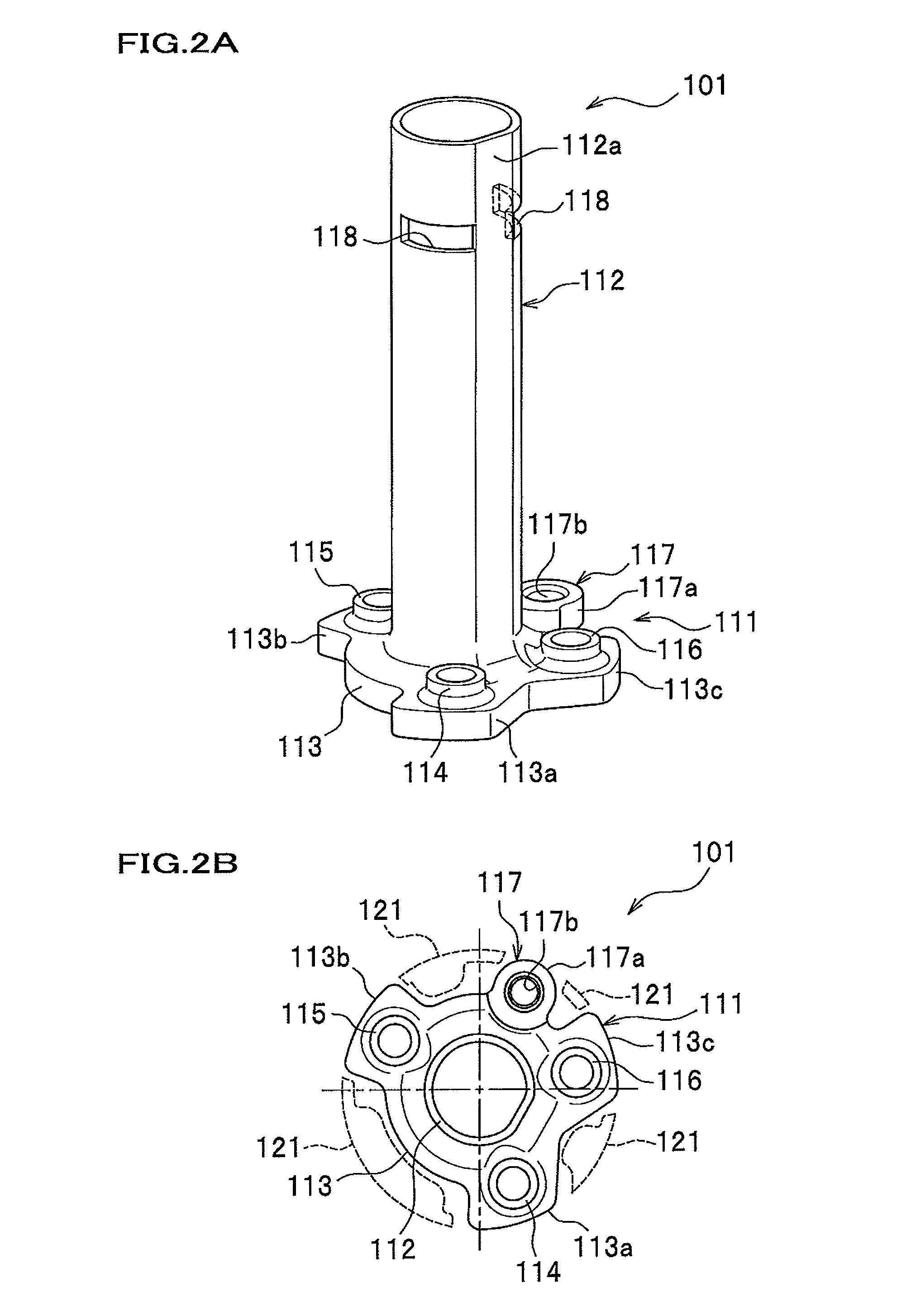
[0072]As shown in FIG. 8, a shaft 3B according to the second embodiment is formed by fitting the first member 101 and a second member 202 together. The first member 101 used herein is the same as that of the first embodiment.

[0073]The second member 202 includes: an outer circumferential portion 221; outer ci...

third embodiment

[0082]Next is described a third embodiment of the present invention. An outer mirror according to the third embodiment has a configuration similar to that of the first embodiment except that the outer mirror rotates by electric motor and is provided with two clutch mechanisms. Thus, in the third embodiment, detailed description is omitted except the shaft and a motor-driven retraction unit attached to the shaft.

[0083]As shown in FIG. 10, a shaft 3C according to the third embodiment is formed by fitting the first member 101 and a second member 302 together. The first member 101 herein used is the same as that of the first embodiment.

[0084]As shown in FIG. 11, the second member 302 includes: an outer circumferential portion 321; outer circumferential opening portions 322a to 322d each opening in a transverse direction at the outer circumferential portion 321; an upper surface 323 forming an upper surface of the outer circumferential portion 321; a cylindrical portion 324 vertically ar...


PUM


Abstract

In a shaft structure of a retractable outer mirror, a shaft includes: a first member; and a second member. The first member includes: a base section having an attachment boss; a shaft section vertically arranged on the base section; and a catch part by which a catch member is caught. The second member includes: clutch parts that performs an engagement or a release of the engagement in response to rotation of a frame; and an insert portion inserted into a shaft section. The second member is fitted in with the shaft section from above a top end side of the shaft section.

Description

CROSS REFERENCE TO RELATED APPLICATION[0001]This application claims the benefit of Japanese Patent Application No. 2009-123521 filed on May 21, 2009, the disclosure of which is incorporated herein by reference.BACKGROUND OF THE INVENTION[0002]1. Field of the Invention[0003]The present invention relates to a retractable outer mirror attached to or near a side door of an automobile.[0004]2. Description of the Related Art[0005]A typically-used retractable outer mirror is attached to a lateral side of an automobile, and its mirror assembly rotates between two positions. The two positions are: a use position at which a mirror surface is at substantially right angles to the lateral side of the automobile; and a retracted position at which the mirror surface is substantially parallel to the lateral side of the automobile.[0006]For example, Japanese Laid-Open Patent Application, Publication No. 2001-287593 (to be referred to as Patent Document 1 hereinafter) discloses an outer mirror which ...

Claims


Application Information

Patent Timeline
Patent Type & Authority Patents(United States)
IPC IPC(8): G02B7/182B60R1/06
CPCB60R1/074B60R1/076
Inventor ITOH, MASAHIKOMATSUSHITA, TAKANOBUHAGIWARA, YUSUKE
Owner MURAKAMI CORP
Why Eureka
Try Eureka