
Applicator with flexible dispensing end

a technology of flexible end and application, which is applied in the direction of pliable tubular containers, hand devices, carpet cleaners, etc., can solve the problems of significant patient morbidity and mortality, broken glass ampoules and dispensing liquids, and financial burdens of the health care system

Active Publication Date: 2012-02-28
AVENT INC
View PDF37 Cites 8 Cited by
  • Summary
  • Abstract
  • Description
  • Claims
  • Application Information

AI Technical Summary

Benefits of technology

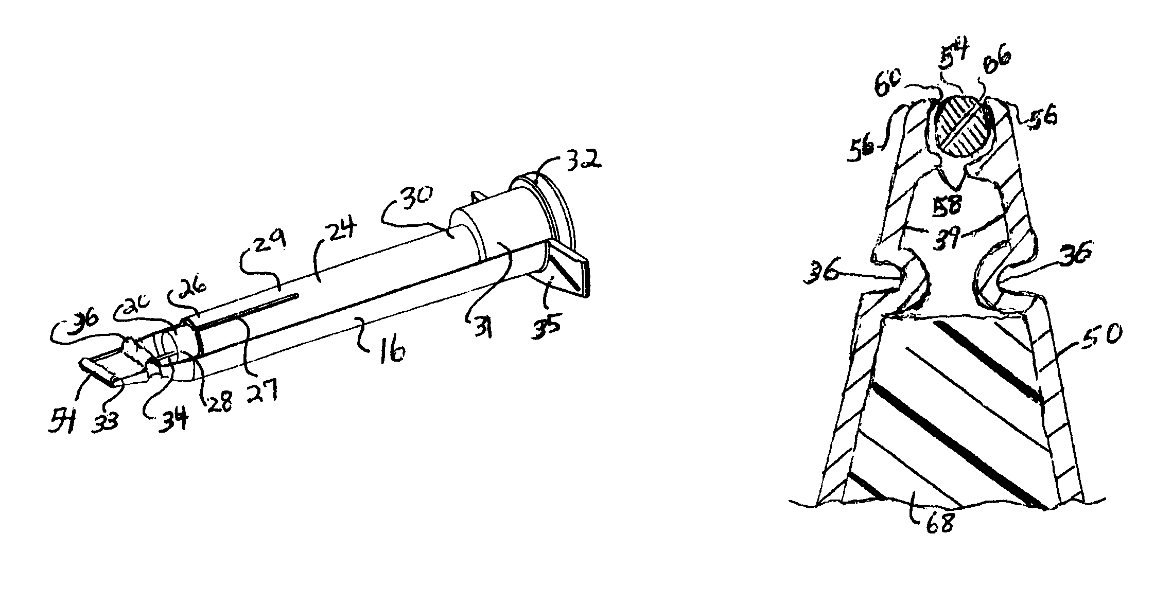
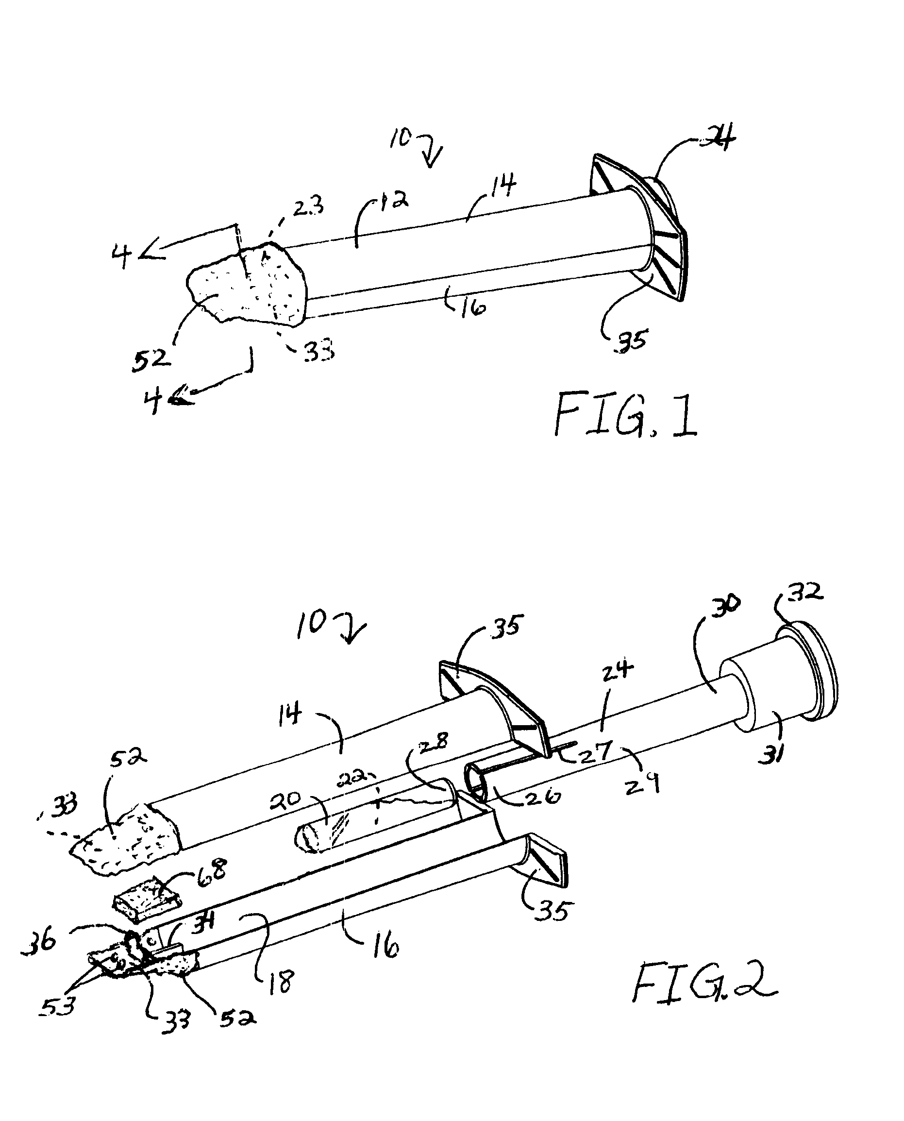
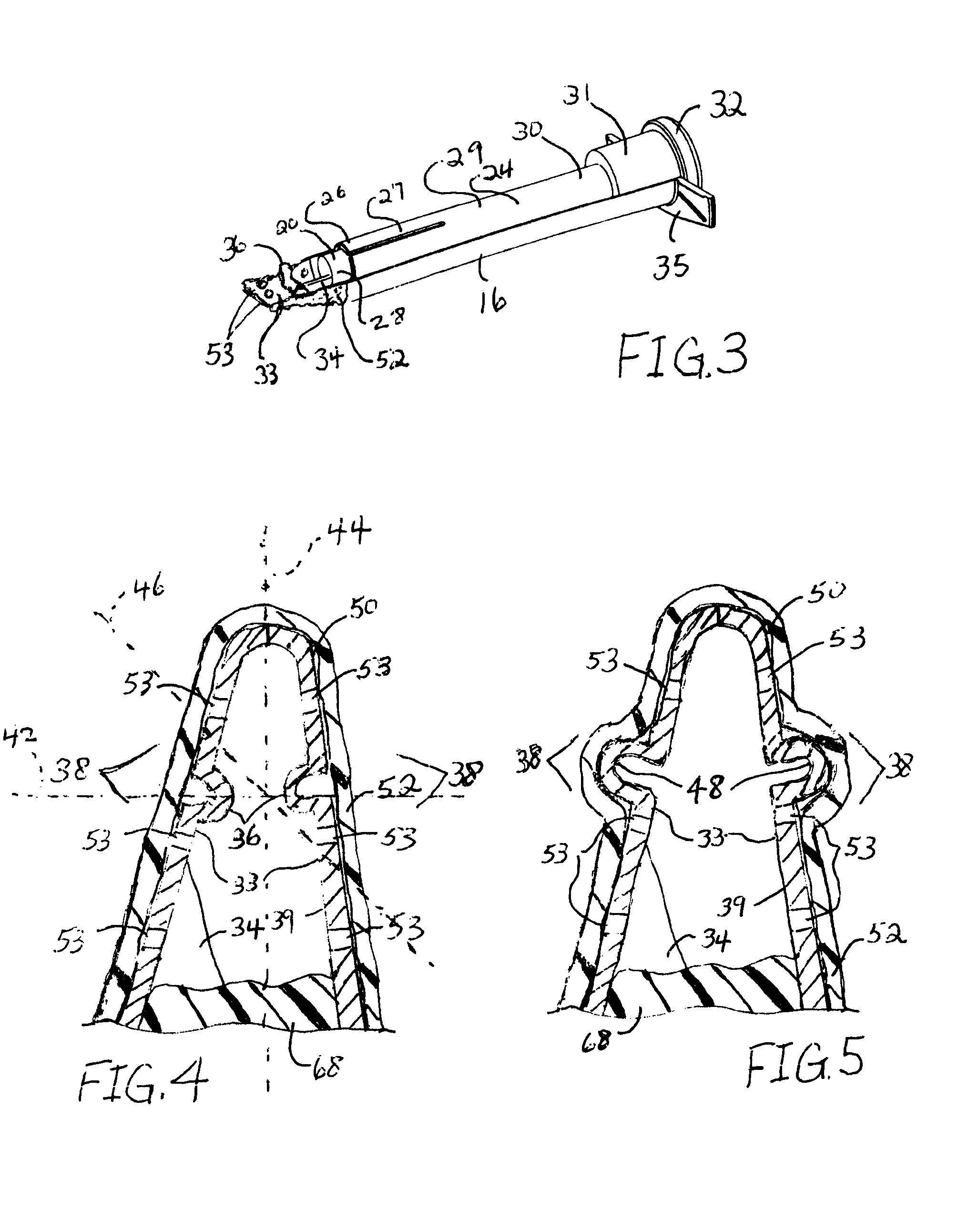
[0012]In another aspect of the invention, an applicator for a skin sealant is provided. The applicator includes an applicator housing formed to include an internal compartment configured to hold a container of skin sealant. The housing includes a dispensing end having at least one opening formed therethrough. The housing also includes an actuator configured to contact the container and release the skin sealant. The dispensing end has at least one movable member such that the dispensing end is flexible and is configured to move on more than one axis when the dispensing end is positioned against a patient's skin. The dispensing end further comprises a porous roller having a plurality of openings formed therethrough. The roller is rotatably held by the dispensing end of the housing. When the skin sealant is released from the container, it flows through the plurality of openings in the roller and the at least one opening surrounding the roller in the dispensing end. The roller is positioned so that when the roller on the dispensing end of the applicator is stroked against a patient's skin, the skin sealant flows around and through at least a portion of the roller such that the skin sealant is uniformly dispensed on a patient's skin via the roller. Pressure applied to the roller and the dispensing end by a user when applying the skin sealant on a patient's skin does not result in abrasions on the patient's skin.

Problems solved by technology

Surgical site infections (SSI) occur following about 2-3 percent of surgeries in the United States with an estimated 500,000 incidents of SSI occurring annually, which can lead to significant patient morbidity and mortality.
In addition to the negative impact of such infections on patient health, these potentially avoidable infections contribute significantly to the financial burden experienced by the health care system.
Time constraints in the operating room and the lack of an indicator that the prep has dried often result in the skin remaining wet when draping and / or surgery begin, creating the possibility of infection.
Moving the parts together results in breakage of the glass ampoule(s) and dispensing of the liquid.
There are several problems, however, with existing dispensing ends which can negatively impact the skin sealant's ability to immobilize bacterial flora found on the skin and prevent their migration into an incision made during a surgical procedure, a skin puncture associated with insertion of an intravenous needle, or a wound.
Problems occur, however, when using the applicator to apply skin sealant to angles, convexities, concavities, and so forth, such as those which are present about a bended knee, bended elbow, fingers, and so forth.
In this instance, because of the rigidity of the dispensing end of the applicator, a smooth, even and regular layer of skin sealant is very difficult or impossible to apply.
This is due to the fact that the dispensing end of the applicator does not flex or bend sufficiently to permit the application of the skin sealant evenly and uniformly into concave areas, such as behind a bended knee, or convex areas, such as over and around a knee cap, and so forth.
Therefore, coverage by the skin sealant is likely to be non-uniform, therefore reducing the ability of the skin sealant to trap and immobilize bacterial flora.
Further, the rigid dispensing end of the applicator, when used aggressively by a user over a convex or concave area, may create small scrapes or abrasions, even though the dispensing end may be covered by a foam or sponge.
Further, the dispensing end, due to the sponge or foam on the dispensing end, cannot be used over sutures or staples covering an incision.
This is due to the foam or sponge catching upon and pulling the sutures or staples.

Method used


Image

  • Applicator with flexible dispensing end
  • Applicator with flexible dispensing end
  • Applicator with flexible dispensing end

Examples


Embodiment Construction

[0034]Reference will now be made in detail to one or more embodiments of the invention, examples of which are illustrated in the drawings. Each example and embodiment is provided by way of explanation of the invention, and is not meant as a limitation of the invention. For example, features illustrated or described as part of one embodiment may be used with another embodiment to yield still a further embodiment. It is intended that the invention include these and other modifications and variations as coming within the scope and spirit of the invention.

[0035]Turning now to the drawings as illustrated in FIGS. 1-10, and in particular, to FIGS. 1-5, an applicator for a skin sealant is provided. As shown in FIGS. 1-3. The applicator 10 includes a housing 12. The housing 12 has a first side wall 14 and a second side wall 16 which are configured to be coupled together to provide the housing 12. The housing 12 has a generally hollow internal compartment 18, which is configured to hold a co...


PUM


Abstract

An applicator with a flexible dispensing end is provided. The applicator includes a housing having an internal compartment configured to hold a container of skin sealant. The housing includes a dispensing end having at least one opening to permit the skin sealant to be dispensed. The housing includes an actuator configured to contact the container and release the skin sealant. The dispensing end has at least one movable member. The dispensing end is flexible and is configured to move on more than one axis, and up to three axes, sequentially or simultaneously, so that the skin sealant dispensed from the applicator may be uniformly applied to contours on a patient's skin.

Description

BACKGROUND[0001]Surgical site infections (SSI) occur following about 2-3 percent of surgeries in the United States with an estimated 500,000 incidents of SSI occurring annually, which can lead to significant patient morbidity and mortality. In addition to the negative impact of such infections on patient health, these potentially avoidable infections contribute significantly to the financial burden experienced by the health care system. SSIs result when an incision becomes contaminated by bacteria, and for most surgeries the primary source of these infection-causing microorganisms is the skin (an exception being surgeries in which the gastrointestinal tract is penetrated).[0002]Various compositions are used to prepare the skin prior to surgery. Skin preparations or “preps” are used to remove some level of microbial load on the skin prior to making an incision. Skin sealant materials are used to protect patients from bacterial infections associated with surgical site incisions and in...

Claims


Application Information

Patent Timeline
Patent Type & Authority Patents(United States)
IPC IPC(8): B43K5/00
CPCA61B17/00491A61M35/006A61B2017/00889
Inventor HOUDE, AJAYOSLUND, SUSAN GAYLEWHITE, TRACY JOSEPHCOCKE, WENDY ANDERSON
Owner AVENT INC
Learn More