Embolic protection system

a protection system and filter body technology, applied in the field of embolism protection filters, can solve the problems of biocompatible coating swelling, low water absorbed, and collapse down, and achieve the effect of preventing adhesion of adjacent folds

Inactive Publication Date: 2012-02-28
SALVIAC
View PDF25 Cites 15 Cited by
  • Summary
  • Abstract
  • Description
  • Claims
  • Application Information

AI Technical Summary

Benefits of technology

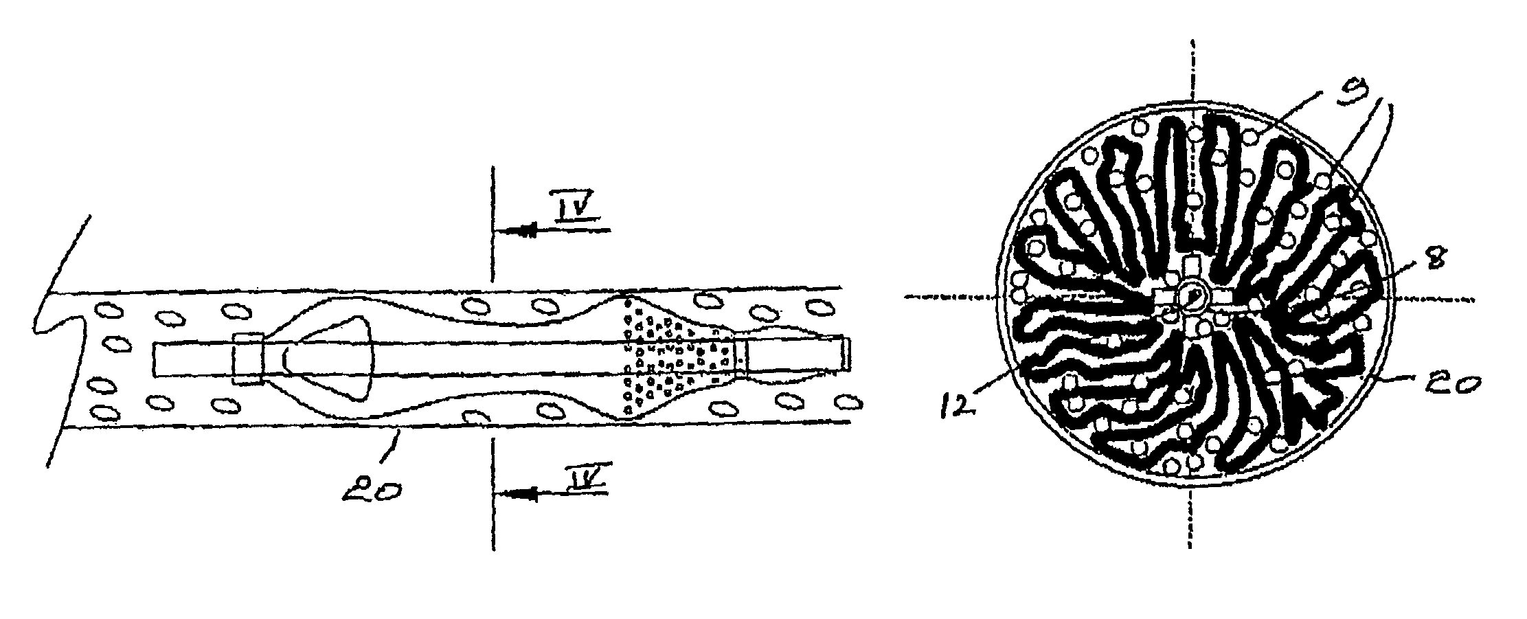
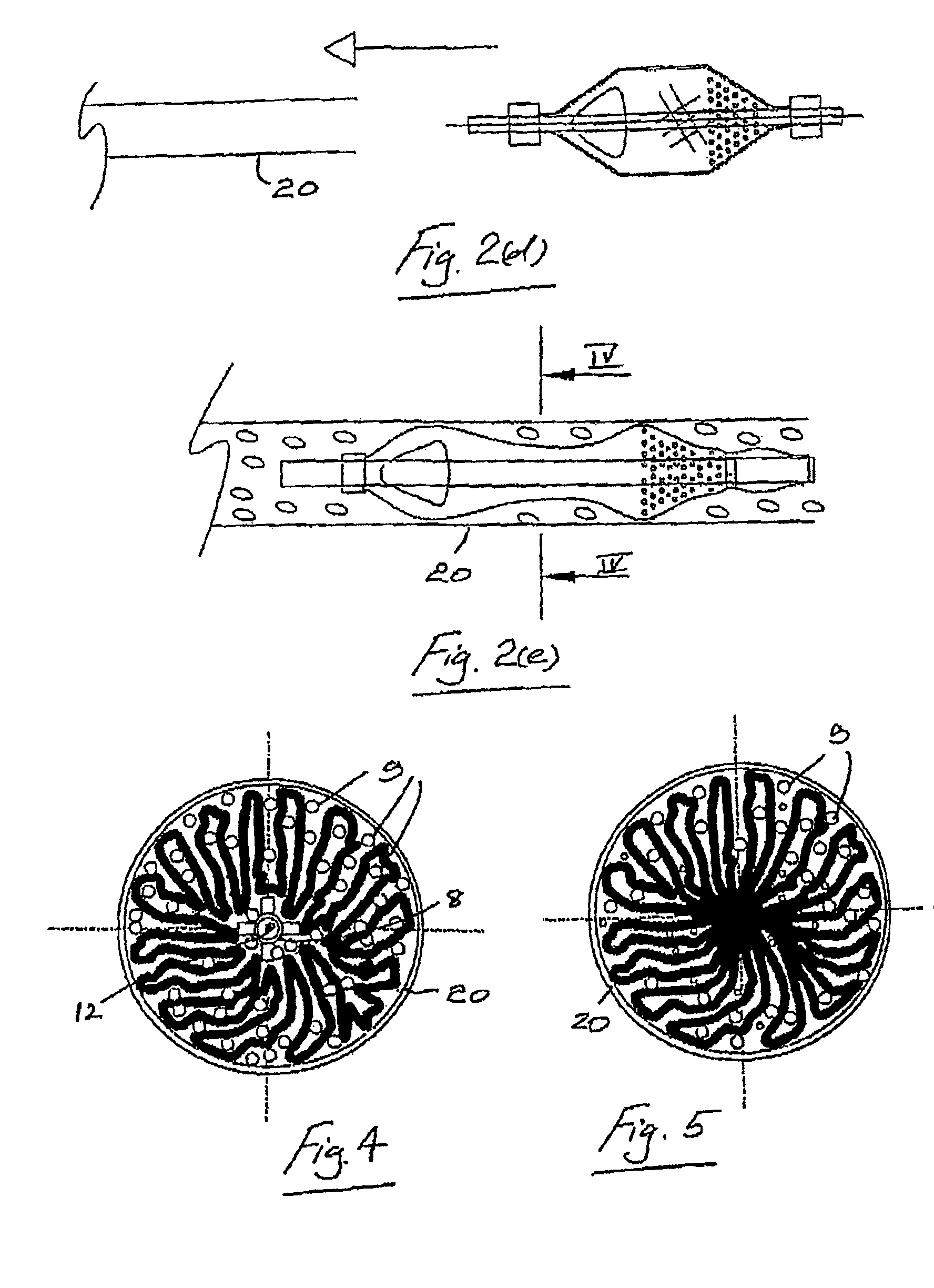
[0014]In another embodiment the system comprises an adhesion preventer to substantially prevent adhesion of adjacent folds of the filter to one another in the collapsed configuration.

Problems solved by technology

It is known to collapse down and load an embolic protection filter into a delivery catheter.
Often the quantity of water absorbed is low leading to the biocompatible coating swelling slightly, and the coating becoming sticky or tacky.
Filter membranes in this state have the potential for self-adherence and this can lead to the collapsed filter becoming stuck to itself in the collapsed configuration with the result that the filter will fail to expand fully, or even expand at all, when deployed in the vasculature.
Failure of an embolic protection filter to correctly deploy in a vasculature can potentially lead to embolic material migrating downstream through the vascular system with potentially life-threatening consequences.
Another problem which arises with a low profile filter loaded into a catheter pod is the difficulty in successfully flushing the device to remove any air.
Because the filter assumes a packed configuration in the pod it is difficult to remove air from the filter.

Method used


Image

  • Embolic protection system
  • Embolic protection system
  • Embolic protection system

Examples


Embodiment Construction

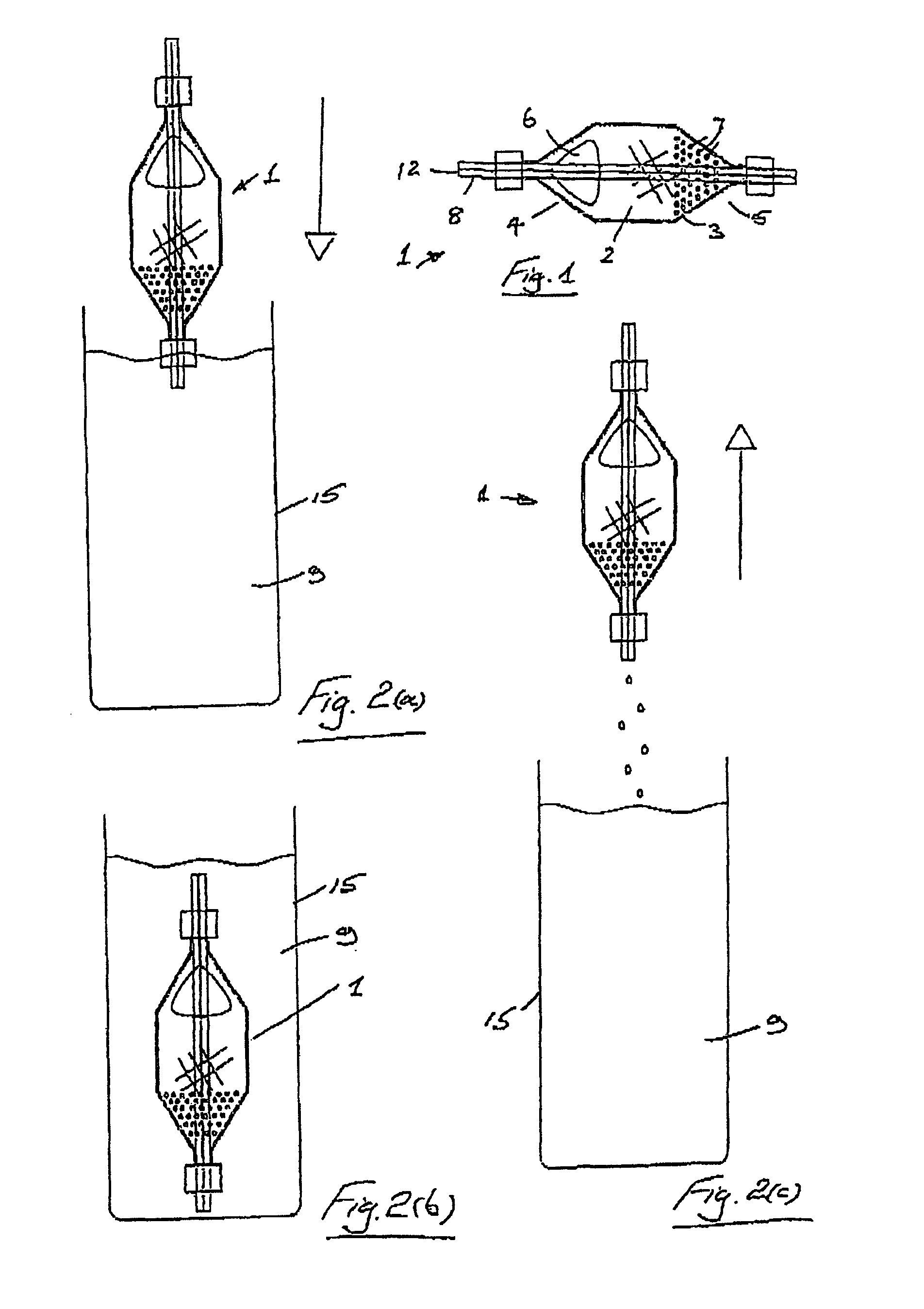
[0145]Referring to the drawings and initially to FIG. 1 thereof, there is illustrated an embolic protection filter 1 which in this case comprises a collapsible filter body 2 and a filter support 3 for the filter body 2. In the embodiment of FIG. 1, the filter body 2 is located externally of the filter support 3. The filter support 3 is mounted around an inner tube 8. The inner tube 8 has a guidewire lumen 12 therethrough, through which a guidewire may pass for exchange of the filter 1 over the guidewire.

[0146]The filter body 2 has an inlet end 4 and an outlet end 5. The inlet end 4 has one or more, and in this case two, large inlet openings 6 which are sized to allow blood and embolic material enter the filter body 2. The outlet end 5 has a plurality of small outlet openings 7 which are sized to allow through passage of blood but to retain undesired embolic material within the filter body 2. In this way, the filter 1 captures and safely retains any undesired embolic material in the ...


PUM


Abstract

An embolic protection system comprises an embolic protection filter 1 having a collapsed delivery configuration and an expanded deployed configuration. The filter 1 is housed in the collapsed configuration in a reception space of a delivery catheter 20. The delivery catheter 20 containing the filter 1 is housed in a sealed sterile pouch 35. The filter 1 may be coated with a non-thrombogenic coating and an adhesion preventer 9 such as a silicon gel is used to substantially prevent adhesion of adjacent folds of the filter 1 when the filter is in the collapsed configuration in the delivery catheter 20.

Description

[0001]This application is a continuation of Ser. No. 10 / 435,661 filed May 12, 2003, now abandoned, which claims benefit of priority under 35 U.S.C. §119(e) to U.S. Provisional Patent Application No. 60 / 378,958, filed May 10, 2002, and all of the disclosures of which are hereby incorporated by reference in their entirety.BACKGROUND OF THE INVENTION[0002]This invention relates to an embolic protection filter, which is movable between a collapsed configuration for transport through a vasculature and an expanded configuration for deployment in a vasculature.[0003]It is known to collapse down and load an embolic protection filter into a delivery catheter. The collapsed filter may then be transported through a vasculature using the delivery catheter until the filter is located at a desired site in the vasculature where the filter may be deployed out of the delivery catheter.[0004]It is also known to coat embolic protection filters with a biocompatible coating to minimize the risk of fibri...

Claims


Application Information

Patent Timeline
Patent Type & Authority Patents(United States)
IPC IPC(8): A61M29/00A61F2/00A61F2/01
CPCA61F2/0095A61F2/01A61F2/013A61F2002/011A61F2230/0006A61F2230/0008A61F2/011A61F2/0108
Inventor BRADY, EAMONFAHEY, GARYCASEY, BRENDANCANNON, ANN MARIEVALE, DAVIDKEEGAN, MARTIN
Owner SALVIAC
Why Eureka
Try Eureka