
Spectroscope

a spectroscope and wavelength resolution technology, applied in the field of spectroscopes, can solve the problems of affecting the wavelength resolution of the spectroscope, the oscillation of the focal length, etc., and achieve the effect of good wavelength resolution

Active Publication Date: 2012-02-28
YOKOGAWA ELECTRIC CORP
View PDF4 Cites 0 Cited by
  • Summary
  • Abstract
  • Description
  • Claims
  • Application Information

AI Technical Summary

Benefits of technology

The present invention provides a spectrocope that can keep good wavelength resolution against changes in the environment temperature without using a special material for the base of the optical components. The spectrocope includes a wavelength dispersion element, a light reception element, and two compound lenses. The linear expansion coefficients of the compound lenses and the material of the base are equal, which enhances the selectivity of materials used for the lenses and the base and eliminates the need for a special material for the base. The spectrocope may also include a wavelength band limiting member or a plurality of photodiodes arranged in a wavelength dispersion direction. The technical effects of the invention include improved accuracy and stability of wavelength measurements and simplified design and manufacturing process.

Problems solved by technology

At this time, there is a problem in that when the ambient temperature changes, the concave mirror expands or shrinks, whereby the focal length fluctuates and the wavelength resolution of the spectroscope worsens.
However, to use soda glass as the material of the concave mirror 2, 4, there is a problem in that a special material with ceramic mixed into aluminum must be used as the material of the base 7 to match the linear expansion coefficients of the concave mirror 2, 4 and the base 7 with each other.

Method used


Image

  • Spectroscope
  • Spectroscope
  • Spectroscope

Examples


Embodiment Construction

[0045]A spectroscope of an embodiment of the invention will be discussed with the accompanying drawings.

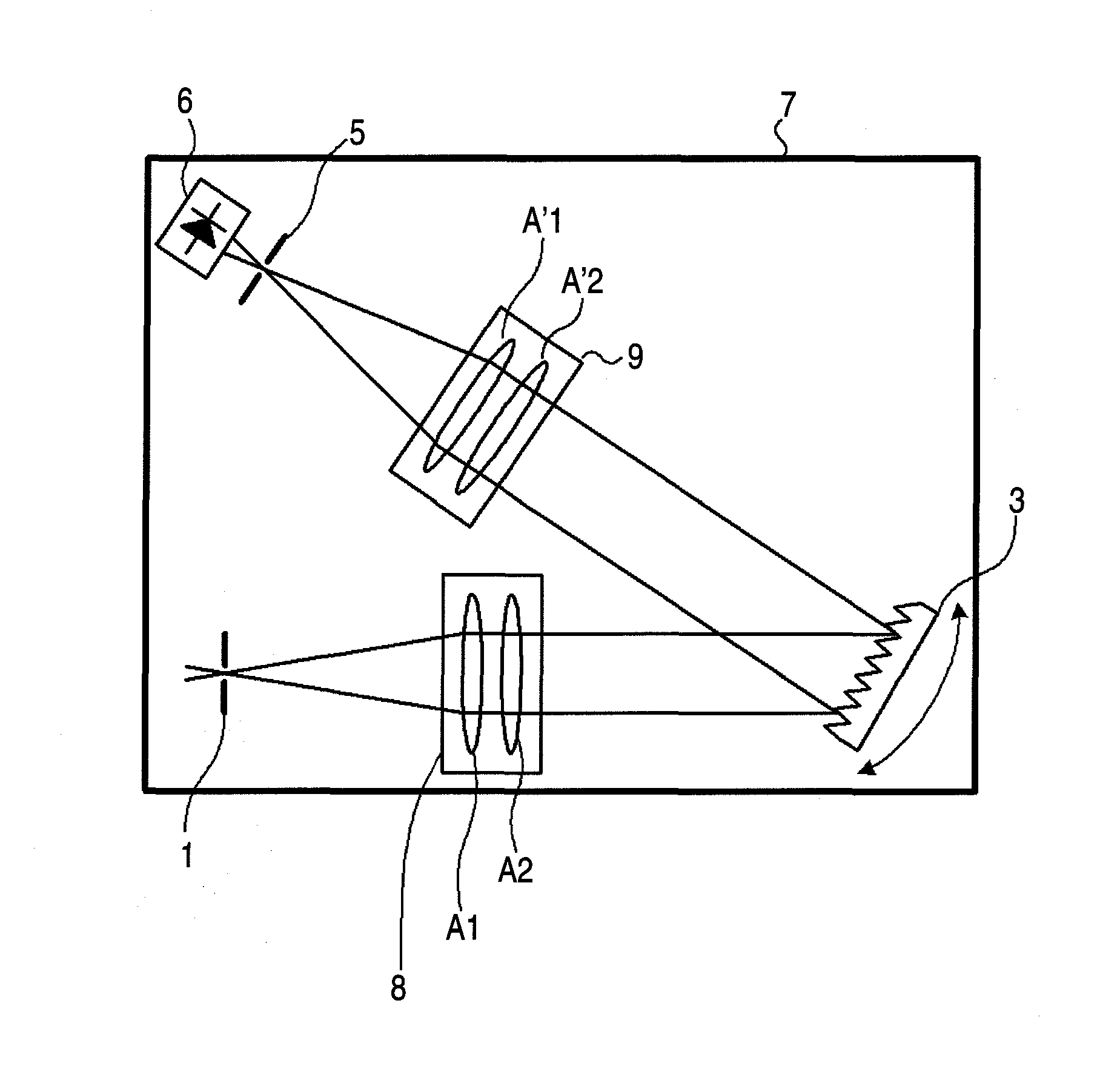
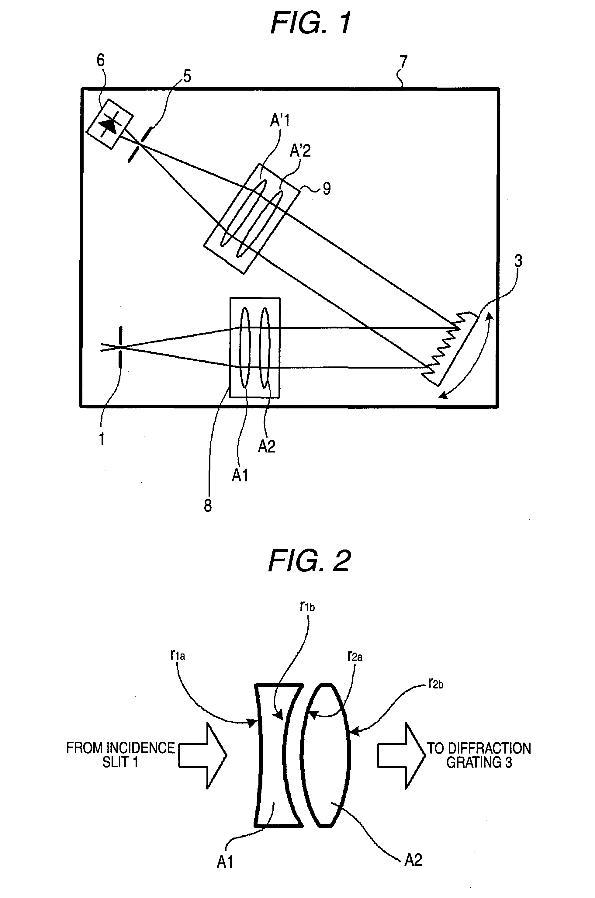
[0046]FIG. 1 is a configuration drawing to show one embodiment of the invention. Components identical with those previously described with reference to FIG. 5 are denoted by the same reference numerals in FIG. 1 and will not be discussed again.

[0047]In FIG. 1, a first compound lens 8 of collimating means is provided between an incidence slit 1 and a diffraction grating 3 in place of the concave mirror 2 in FIG. 5. The first compound lens 8 is made up of two lenses A1 and A2 for converting measured light passing through the incidence slit 1 into parallel light and emitting the parallel light to the diffraction grating 3. The lens A1 is provided on the side of the incidence slit 1 and the lens A2 is provided on the side of the diffraction grating 3.

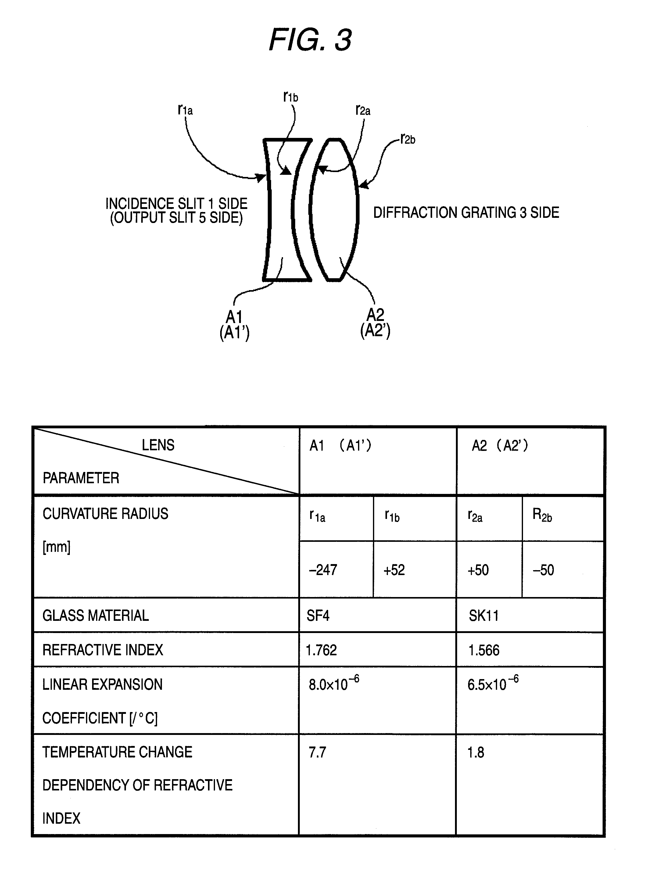
[0048]A second compound lens 9 of light gathering means is provided between the diffraction grating 3 and an output slit 5 in place of t...


PUM


Abstract

An improvement is added to a spectroscope for performing wavelength dispersion of measured light with a wavelength dispersion element and receiving the light at a light reception element. The spectroscope has a first compound lens made up of a plurality of lenses for converting measured light into parallel light and emitting the parallel light to the wavelength dispersion element; a second compound lens made up of a plurality of lenses for gathering the measured light subjected to the wavelength dispersion in the wavelength dispersion element and causing the light reception element to receive the light; and a base for fixing the wavelength dispersion element, the first compound lens, and the second compound lens. The linear expansion coefficient of the compound focal length of the first compound lens, the linear expansion coefficient of the compound focal length of the second compound lens, and the linear expansion coefficient of a material forming the base are substantially equal.

Description

TECHNICAL FIELD[0001]The present disclosure relates to a spectroscope for performing wavelength dispersion of measured light with a wavelength dispersion element and receiving the light at a light reception element and more particularly to a spectroscope for keeping good wavelength resolution against change in the environment temperature without using a special material for a base for fixing optical components.RELATED ART[0002]A spectroscope performs wavelength dispersion of measured light with a wavelength dispersion element (for example, a diffraction grating) and measures light power for each wavelength with a light reception element. The spectroscope converts the measured light incident on the spectroscope into parallel light using collimating means (for example, a concave mirror), emits the parallel light to a diffraction grating, gathers diffracted light from the diffraction grating using light gathering means (for example, a concave mirror), and receives the light at the ligh...

Claims


Application Information

Patent Timeline
Patent Type & Authority Patents(United States)
IPC IPC(8): G01J3/28
CPCG01J3/02G01J3/0208G01J3/0286G01J3/0291
Inventor YAMAMOTO, TOSHIKAZUKANEKO, TSUTOMUKOJIMA, MANABU
Owner YOKOGAWA ELECTRIC CORP
Learn More