Linear actuator

Active Publication Date: 2012-03-06
LINAK AS
View PDF13 Cites 0 Cited by
  • Summary
  • Abstract
  • Description
  • Claims
  • Application Information

AI Technical Summary

Benefits of technology

[0011]In a special embodiment the end-stop switches are designed as two parallel pieces of conductors, and where the connection element is equipped with an electric conductive element for creating contact between these conductors placed in pairs in the respective outer positions of the spindle nut. This is a simple, inexpensive and reliable solution. The conductors are, expediently, printed paths on the circuit board.
[0013]Expediently, the conductive element is a roll, which provides for a low wear on the conductors.
[0016]The connection element is typically longer than the circuit board, for which reason it is, expediently, constructed with hinges, so that it is collapsible, so that it does not project from the ends of the circuit board. In that way, it is ensured that the connection element does not get damaged during the handling and the shipment. The connection element need not be unfolded until the moment that it is to be affixed to the spindle nut.
[0017]A special type of linear actuator with a drive in each end is for instance known from DE 38 42 078 C2 to Dietmar Koch, EP 0 372 032 B2 to Eckhart Dewert and WO 2005 / 122840 A1 to Linak A / S. This type of linear actuator (dual actuator) is used in beds and armchairs for adjusting the back rest and leg rest section, back and seat, respectively. In this type of actuator the circuit board with the control electronics and the switch is placed between the two drives. Only one single switch is necessary for instance one single switch by beds for the drive for the back rest section in case the two sections are arranged to run interdependent of each other, for example that the leg rest section is forcible controlled proportionally to the back rest section. Opportune, a switch is arranged in connection with a drive each, which provides a basis for a simpler controlling and that the sections can be controlled individually. It also provides for enhanced safety, that the section does not exceed its motion path.

Problems solved by technology

The construction has the obvious disadvantage that it is heavy loaded in the outer positions.
Here, it is not possible to detect an intermediate position either.
This is of course a more expensive solution than simple end-stop switches.
Moreover, the rotary potentiometer has the disadvantage that it can be turned excessively, which causes an incorrect determination of the position.
The magnetic and optical encoder has the disadvantage that the position is lost if the spindle begins rotation on its own.
When the actuator stops in an intermediate position, it can rotate a little backwards, or it can rotate backwards as a result of failure in the self-locking ability of the actuator, for example by over load or vibrations in the construction.

Method used


Image

  • Linear actuator
  • Linear actuator
  • Linear actuator

Examples


Embodiment Construction

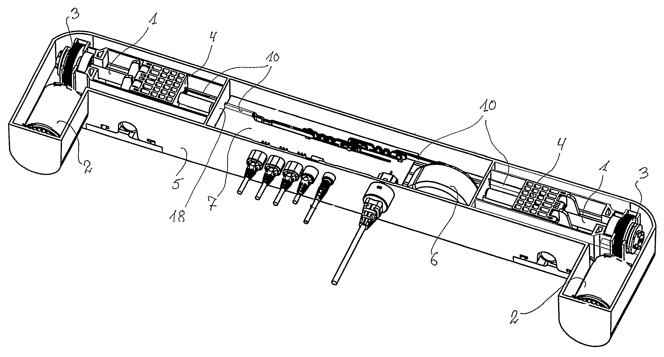
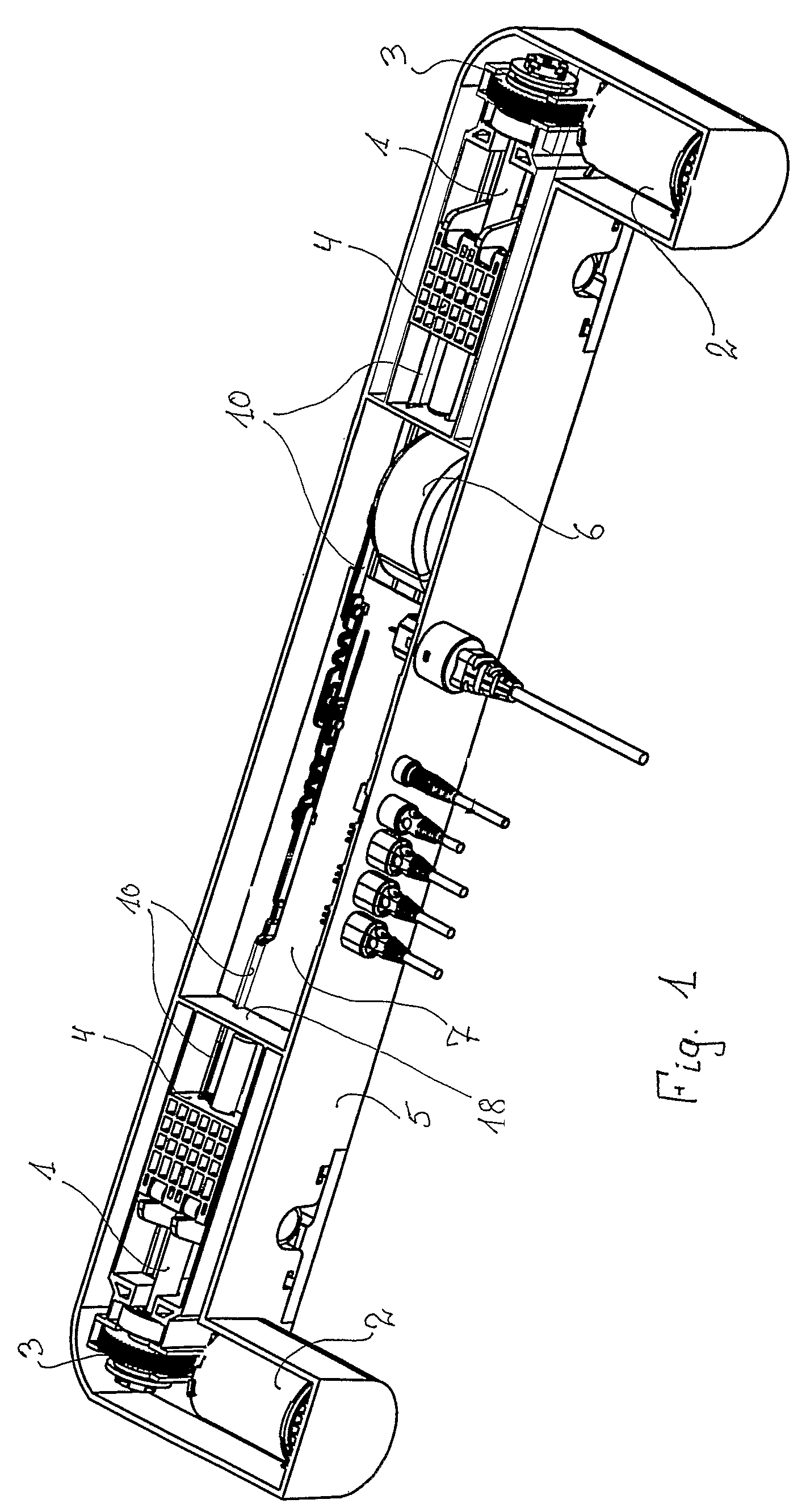
[0024]The linear dual actuator shown in FIG. 1 is intended for adjustable beds, where a uniform drive unit is provided in each end of the actuator. These drive units comprise a spindle 1 driven by a low voltage DC motor 2 over a worm drive 3. A spindle nut 4 shaped as a square like sliding element is mounted on the spindle 1 and guided in the housing of the actuator 5, so that it is prevented from rotating, which causes it to slide back and forth on the spindle 1 depending on the direction of rotation of the spindle. In the middle of the housing 5 a power supply based on a toroidal transformer 6 and a control circuit board 7 is mounted.

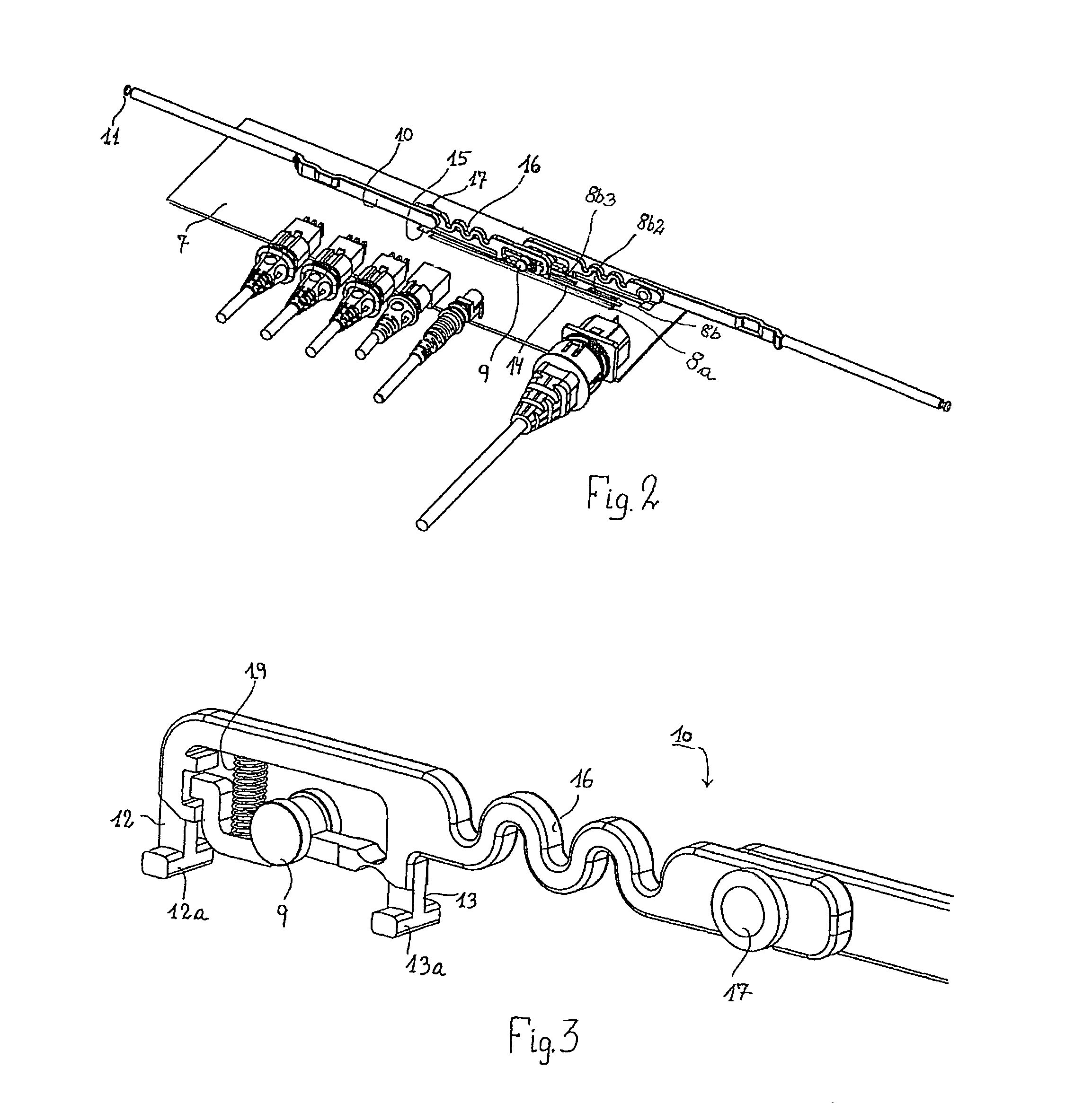
[0025]The end-stops for the travel of the spindle nut is integrated into the circuit board 7, which have two parallel paths in the nature of printed conductors 8. Through a metal roller 9 mounted on the end of the connection rod 10 contact in pairs is created between these conductors 8. The metal roller 9 is mounted on an arm, which is pressed in cont...


PUM


Abstract

By a linear actuator of the type comprising a driven spindle with a spindle nut, the outer positions and possibly also the intermediate positions of the spindle nut can be determined by a specially designed switch construction. This switch comprises an elongated conductor (8a), and next to this at least one other short conductor (8b), and where a connection element (10) for the spindle nut is equipped with an electric conductive element (9), for creating contact between the two conductors (8a, 8b). With two short conductors at the end of the elongated conductor end-stop switches for the nut are achieved and with more short conductors between the two end conductors the position of the spindle nut between its outer positions can be determined.

Description

BACKGROUND OF THE INVENTION[0001]1. Field of the Invention[0002]The present invention relates to a linear actuator wherein an electric motor drives a spindle and the spindle is provided with a spindle nut secured against rotation, which directly, as for example indicated in EP 0 787 267 B1 to Dietmar Koch (OKIN), or which over a tube-shaped actuation rod, as indicated in EP 1 322 876 B1 to LINAK A / S, is connected to an adjustable element for adjusting the same.[0003]2. The Prior Art[0004]The fully extended positions of the spindle nut can be determined in various ways. Typically this can be achieved by means of end-stop switches, which determine the inner and outer position of the spindle nut. As for instance mentioned in EP 1 322 876 B1, this can be brought about with a strip-shaped circuit board equipped with end-stop switches at each end. The circuit board is arranged in parallel to the spindle and in the track of the spindle nut, so that the spindle nut activates the switches in...

Claims


Application Information

Patent Timeline
IPC IPC(8): F16H3/06F16H29/02F16H27/02F16H29/20
CPCF16H25/2015Y10T74/18688Y10T74/18576F16H2025/2084
Inventor KRISTENSEN, HENNING
Owner LINAK AS
Why Eureka
Try Eureka