Air gun and magazine for air gun

a technology of air gun and air gun magazine, which is applied in the direction of compressed gas guns, white arms/cold weapons, weapons, etc., can solve the problems of increased manufacturing cost and increased production cost, and achieve the effect of reducing the speed of bullets, reducing manufacturing costs, and reducing manufacturing costs

Inactive Publication Date: 2012-03-06
MARUZEN
View PDF5 Cites 6 Cited by
  • Summary
  • Abstract
  • Description
  • Claims
  • Application Information

AI Technical Summary

Benefits of technology

[0026]According to the present invention, by providing an extremely simple member such as a partition wall having a microscopic hole section, it is possible to reliably reduce the speed of a bullet to within a fixed speed, even a complicated decompression device such as a regulator is not provided. As a result, manufacturing time for the air gun is shortened, it is possible to lower manufacturing cost, and there is the effect of improving the manufacturing efficiency.
[0027]This is because with an air gun or a magazine for an air gun of the present invention, by having a structure where the opening area of the microscopic hole section of the partition wall is smaller that the gas discharge path opening when the gas discharge path of the discharge valve is open, the gas volume per unit time that flows into the discharge valve chamber from the gas canister side by means of the microscopic holes section is smaller than the gas volume per unit time that flow out from the discharge valve chamber as a result of opening the gas discharge path of the discharge valve, which means that gas speed and gas pressure from the discharge valve chamber to the chamber where a bullet is positioned is lowered. The firing speed of a bullet is thus reduced.

Problems solved by technology

Since the gas pressure discharged from the gas canister is high pressure (about 70 atmospheres), there is a problem in that if that pressure is used directly the bullet speed would be too fast.
There is therefore a problem in that costs are incurred, such as processing time and procurement of components in order to provide the regulator.

Method used


Image

  • Air gun and magazine for air gun
  • Air gun and magazine for air gun
  • Air gun and magazine for air gun

Examples


Embodiment Construction

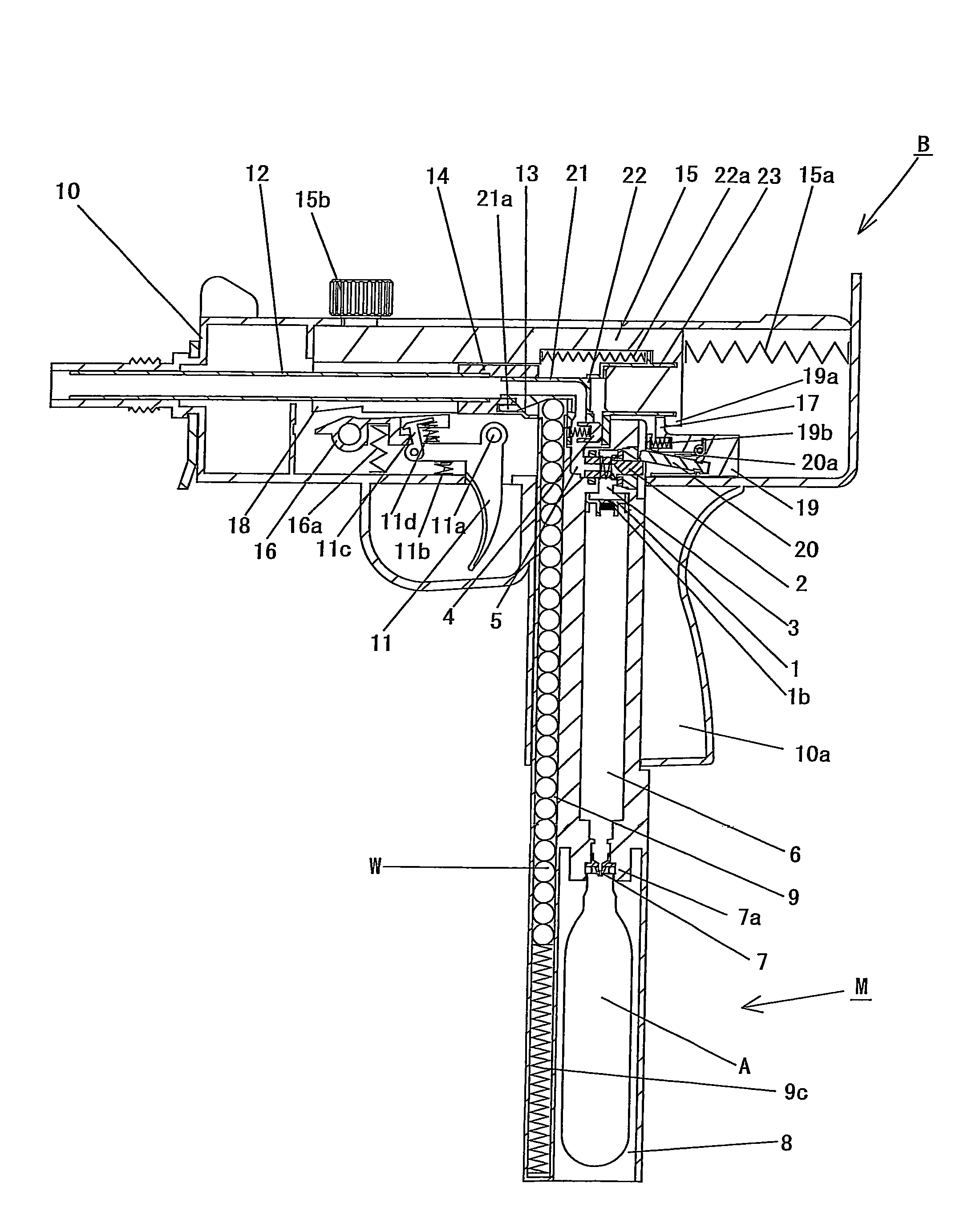
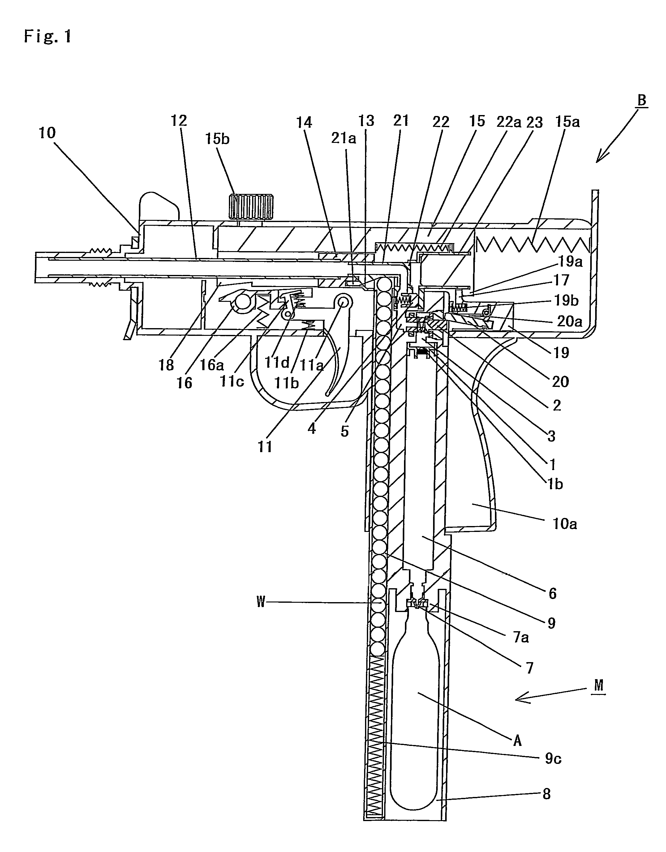
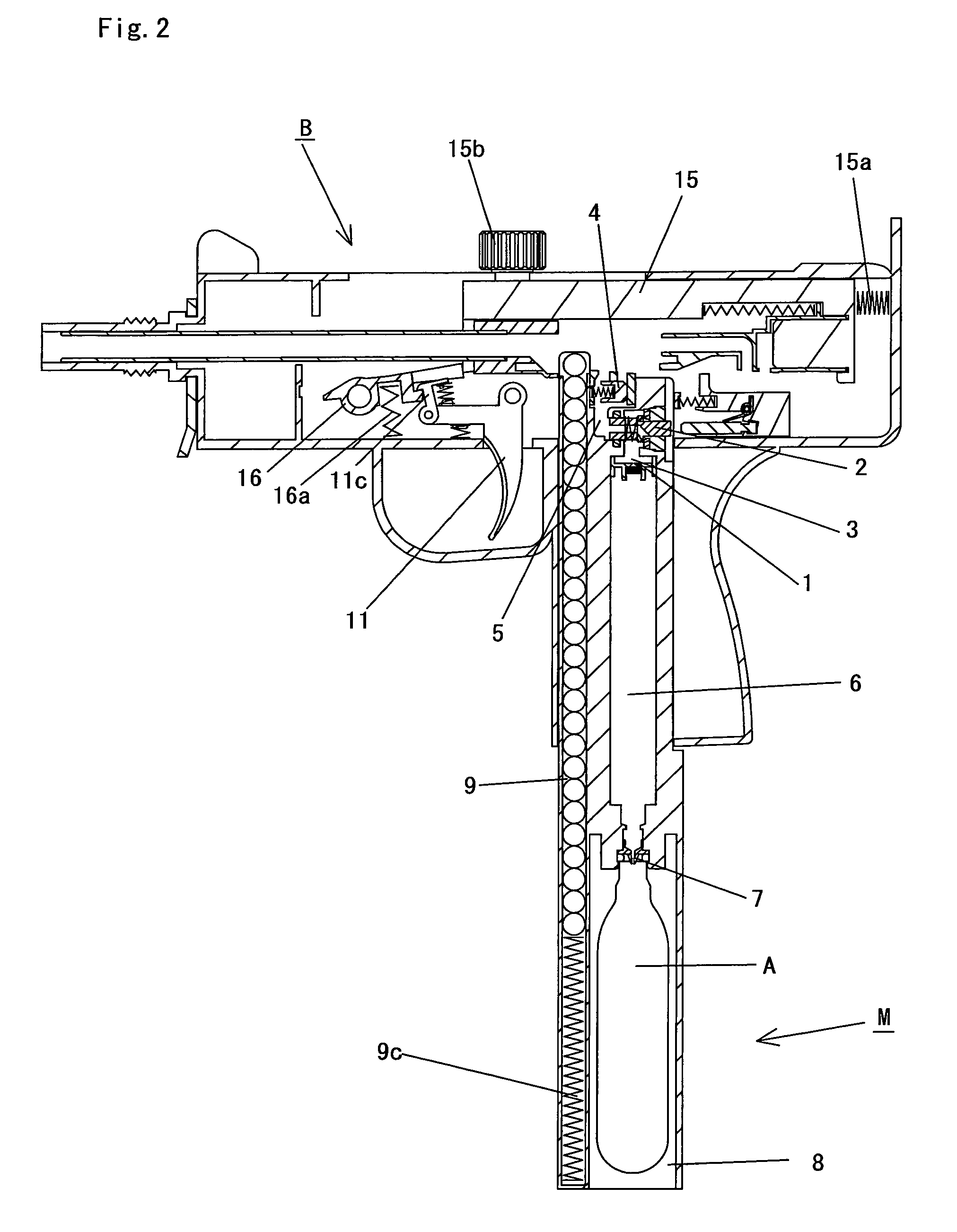
[0044]Description will now be given based on FIG. 1 to FIG. 25 that show one embodiment of an air gun and a magazine for an air gun of this invention. The air gun shown in FIG. 1 to FIG. 24 is an air gun for firing of a bullet W using compressed air, and carrying out blowback, and has a vaporization chamber 6. Besides an air gun of this configuration, it is also possible to utilize an air gun having a vaporization chamber 6 that fires a bullet W using compressed gas but does not perform blowback, an air gun that does not have a vaporization chamber 6 and carries out blowback together with firing of a bullet W using compressed gas (FIG. 25), and an air gun that does not have a vaporization chamber 6 and fires a bullet W but does not carry out blowback.

[0045]In FIG. 1 to FIG. 25, as an embodiment of this invention, description will be given for an air gun constructed with a partition wall 1 and a discharge valve 2 etc. are provided in a magazine M, and with the magazine M capable of b...


PUM


Abstract

According to the present invention, by providing an extremely simple member such as a partition wall having a microscopic hole section, it is possible to reliably reduce the speed of a bullet to within a fixed speed, even a complicated decompression device such as a regulator is not provided. As a result, manufacturing time for the air gun is shortened, it is possible to lower manufacturing cost, and there is the effect of improving the manufacturing efficiency.This is because with an air gun or a magazine for an air gun of the present invention, by having a structure where the opening area of the microscopic hole section of the partition wall is smaller that the gas discharge path opening when the gas discharge path of the discharge valve is open, the gas volume per unit time that flows into the discharge valve chamber from the gas canister side by means of the microscopic holes section is smaller than the gas volume per unit time that flow out from the discharge valve chamber as a result of opening the gas discharge path of the discharge valve, which means that gas speed and gas pressure from the discharge valve chamber to the chamber where a bullet is positioned is lowered. The firing speed of a bullet is thus reduced.

Description

BACKGROUND OF THE INVENTION[0001]1. Field of the Invention[0002]The present invention relates to an air gun for firing bullets with compressed air as an energy source, and also relates to an air gun for performing firing and blowback, and to a magazine for an air gun capable of being fitted into such air guns.[0003]2. Description of the Related Art[0004]An air gun for firing bullets using compressed air, and an air gun for carrying out both firing of bullets and blowback are known. A magazine capable of being fitted into these air guns is also known.[0005]A normal air gun is generally constructed to fire bullets utilizing ejection pressure of a gas canister fitted to a magazine. Gas that has been discharged from a gas canister passes through a discharge valve chamber, which is a space formed between a discharge valve and piercing assembly, due to the pressure of the gas, and a bullet positioned in a chamber is fired by opening the discharge valve (refer to related art 1, FIG. 26).[0...

Claims


Application Information

Patent Timeline
Patent Type & Authority Patents(United States)
IPC IPC(8): F41B11/00F41B11/72
CPCF41B11/724
Inventor MAEDA, TETSUO
Owner MARUZEN
Why Eureka
Try Eureka