High-lift device for an aircraft

a technology of high-lift devices and aircraft, which is applied in the field of aircraft, can solve the problems of affecting the air flow over the wing, reducing the maximum lift coefficient, increasing drag, and often only being reliably achieved with the addition of considerable weight, complexity and cost, and achieving the effect of significantly reducing the rate of air flowing past the vortex generator, reducing the component of flow, and increasing the streamwise component of flow

Active Publication Date: 2012-03-06
AIRBUS OPERATIONS LTD
View PDF16 Cites 6 Cited by
  • Summary
  • Abstract
  • Description
  • Claims
  • Application Information

AI Technical Summary

Benefits of technology

[0028]Preferably, the rate of air flowing past the vortex generators is significantly reduced when the drooped leading edge flap is moved from the deployed position to the stowed position. For example, the vortex generators may be covered by part of the drooped leading edge flap when the drooped leading edge flap is in the stowed position. Advantageously, in certain embodiments of the invention, the vortex generators are shielded from most, and preferably any, air flow, when the drooped leading edge flap is in the stowed position.
[0029]Advantageously, in certain embodiments of the invention, the drooped leading edge flap further comprises a turning vane, wherein said turning vane is arranged to direct flow having a component of flow in the wing root-to-tip direction, so as to reduce the component of flow in the wing root-to-tip direction. Preferably the turning vane is arranged to increase the streamwise component of the flow. The turning vane may be arranged to increase the chordwise component of the flow. It will be understood that the turning vane may be any element used to direct flow towards a given direction. The turning vane is conveniently located such that at least some air flows via the turning vane before exiting out of the opening. In the case where the opening comprises a cavity, the turning vane is preferably located within the cavity. The turning vane is preferably fixedly mounted on the drooped leading edge flap. In an embodiment described below, the t

Problems solved by technology

This is due to the deployed leading edge being better aligned to the freestream such that the flow does not negotiate the relatively low radius of curvature of the clean leading edge.
If the design of the drooped leading edge flap were such that a discontinuity could be formed between the upper trailing edge of the drooped leading edge fla

Method used


Image

  • High-lift device for an aircraft
  • High-lift device for an aircraft
  • High-lift device for an aircraft

Examples


first embodiment

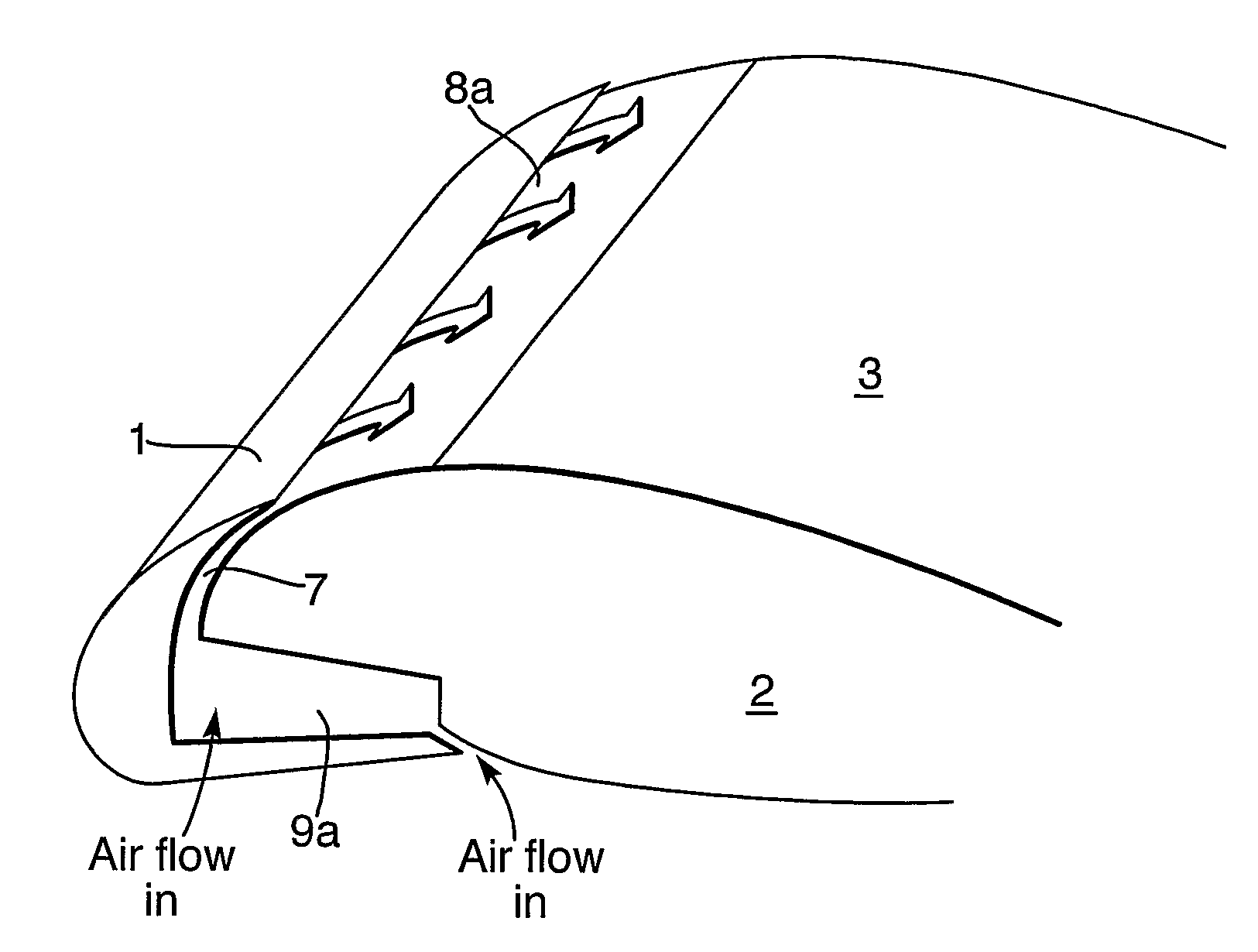
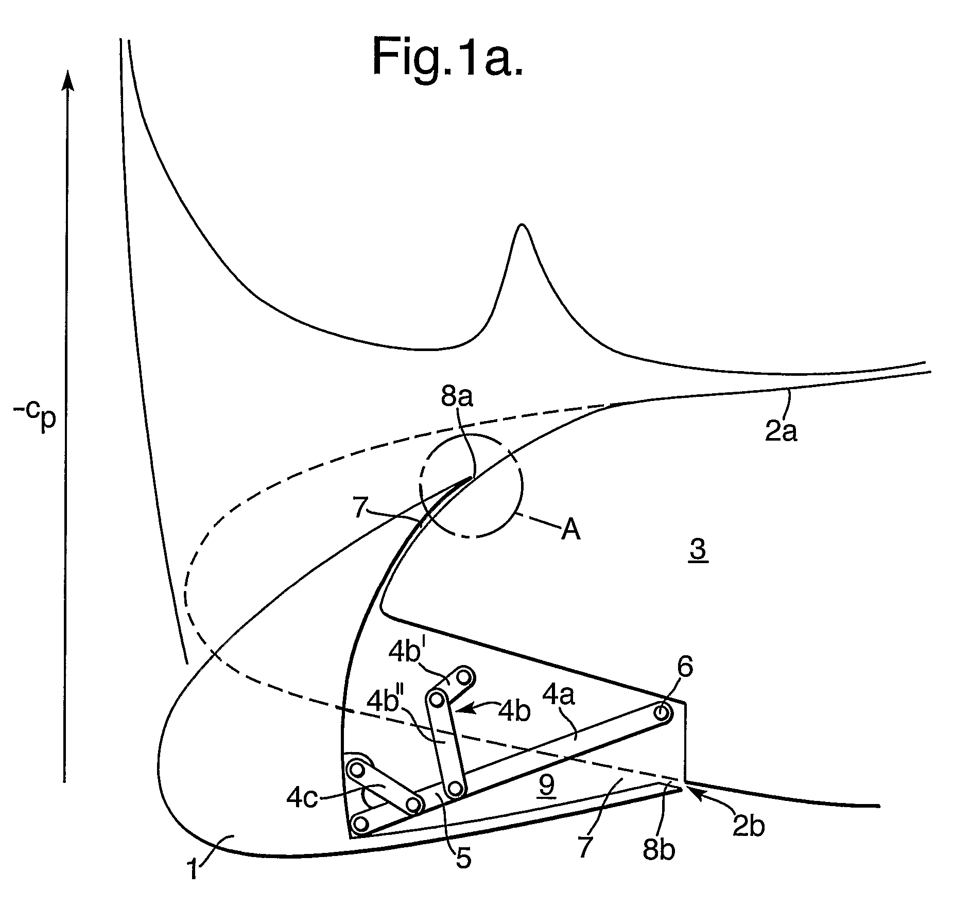
[0044]In the deployed position, there exists an opening 7 between the drooped leading edge flap 1 and the adjacent main wing portion 3. The opening 7 is in the form of a gap, the gap comprising slots 8a &8b on the upper and lower surfaces of the wing 2 respectively, and further including the cavity 9. An upper trailing edge and a lower trailing edge of the drooped leading edge flap 1 are immediately adjacent to the main wing portion 3 and define an upper gap (slot 8a) and a lower gap (slot 8b), respectively, to thereby define a cavity 9 between the drooped leading edge flap 1 and the main wing portion 3. In the invention, the cavity is open at both spanwise ends 9a and 9b.

[0045]During flight, the local pressure on the upper surface 2a of the wing 2 is lower than the local pressure on the lower surface 2b of the wing 2, and lower than the local pressure at the spanwise ends 9a and 9b of the drooped leading edge flap 1. As a result of this pressure differential, air flows from the lo...

second embodiment

[0051]FIG. 3 shows an aircraft wing according to the invention. A drooped leading edge flap 101 is located on the wing 102, inboard of the engine nacelle 15, which is supported on the engine pylon 17. Outboard of the engine nacelle 15, there is located a midboard section slat 19.

[0052]The drooped leading edge flap 101 is moved from the stowed position (not shown) towards the deployed position (the position in which it is shown in FIG. 3) by using an actuator (not shown) located within the wing 102. When the drooped leading edge flap 101 is deployed, a region 20 on the upper surface of the adjacent main portion of the wing 103 is exposed.

[0053]During flight, a pressure differential occurs between the upper and lower surfaces of the wing. During certain flight conditions when the drooped leading edge flap is in the deployed position, the wing 102 generates an aerodynamic force of sufficient magnitude and direction, such that the drooped leading edge flap 101 is caused to lift away fro...

fourth embodiment

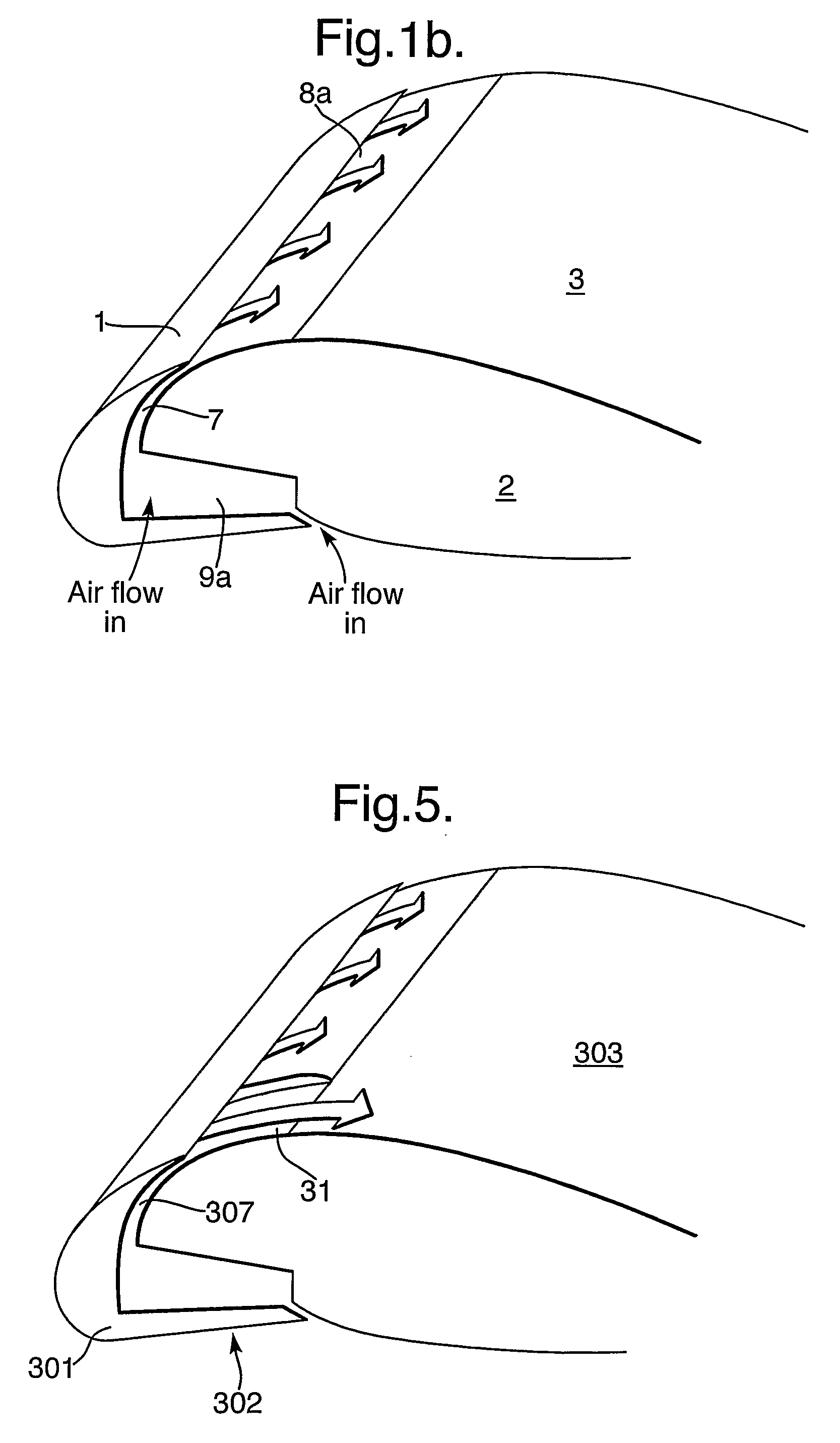
[0059]FIG. 5 shows a wing 302 according to the invention. The large arrows indicate movement of air. The dimensions of the opening 307 are increased at the outboard end of the drooped leading edge flap 301. This is achieved by locally reshaping the leading edge 31 of the main wing portion 303 in this region. This allows an increased mass flow of air through the part of the opening 7 in this region, delivering even more energetic flow into, and further stabilising, the boundary layer. The outboard end of the drooped leading edge flap 301 is located near an engine pylon (not shown) and the drooped leading edge flap therefore stabilises the flow in this critical region.

[0060]It will be appreciated that various modifications may be made to the above-described embodiments of the invention. For example, the feature of the net aerodynamic force effecting movement of the drooped leading edge flap and thereby creating an opening (as described in relation to the second embodiment), need not n...


PUM


Abstract

An aircraft comprises a wing (2) defining an aerofoil surface, the wing (2) comprising a drooped leading edge flap (1) being moveable between a stowed position and a deployed position. The wing (2) is so arranged that during flight when the high-lift device is in the deployed position, air may flow through an opening (7) in the wing (2) and over the aerofoil surface. During flight, air preferably flows into the boundary layer (13) on the upper surface of the wing (2). This energises the boundary layer (13), aft of the trailing edge of the drooped leading edge flap increasing its stability allowing the maximum achievable lift coefficient to be increased and hence reducing aircraft take-off and approach speeds.

Description

RELATED APPLICATIONS[0001]The present application is a National Phase entry of PCT Application No. PCT / GB2005 / 001730, filed May 9, 2005, which claims priority from, British Application Number 0410375.0, filed May 10, 2004, the disclosures of which are hereby incorporated by reference herein in their entirety.TECHNICAL FIELD[0002]This invention relates to aircraft, and in particular, but not exclusively to those having high-lift leading edge devices and to the use thereof.BACKGROUND OF THE INVENTION[0003]High-lift leading edge devices are often used on an aircraft to increase the available maximum lift, particularly during take-off and landing. Two known high-lift leading edge devices are the slat and the drooped leading edge flap.[0004]Slats are generally moveable between a retracted position in which the slat is located against the leading edge of the wing and a deployed position in which the slat is deployed downwards and forwards away from the main portion of the wing. The intera...

Claims


Application Information

Patent Timeline
IPC IPC(8): B64C3/50B64C9/22B64C9/24
CPCB64C9/24B64C23/06Y02T50/32Y02T50/44Y02T50/162Y02T50/10Y02T50/30Y02T50/40
Inventor WHITEHOUSE, IAN ROYKAY, EDMUNDDODD, DANIEL
Owner AIRBUS OPERATIONS LTD
Why Eureka
Try Eureka