Lighting apparatus

a technology of light source and light source, which is applied in the direction of identification means, domestic cooling devices, furnaces, etc., can solve the problems of mercury poisoning, high energy consumption, and difficulty in activation, and achieve the effects of avoiding mercury poisoning, reducing energy consumption, and reducing energy consumption

Active Publication Date: 2012-03-06
IND TECH RES INST
View PDF9 Cites 14 Cited by
  • Summary
  • Abstract
  • Description
  • Claims
  • Application Information

AI Technical Summary

Benefits of technology

[0007]Compared with fluorescent lamps, light emitting diodes (LEDs) have longer lifetime and provide higher color rendering index with adjustable color temperature. Besides, LEDs are free from the risk of mercury poisoning, and have better luminous efficiency even under low temperature. Thus, the drawbacks with fluorescent lamps will be overcome when LEDs are used in a refrigerated display cabinet instead. To utilize energy more efficiently, the present invention takes advantage of the directional nature pertaining to LED lighting to avoid dissipation of light energy and thus increase luminous efficiency. As such, an object of the present invention is to provide a lighting apparatus, which, compared with a conventional fluorescent lamp, is more compact in size and has simpler structure that makes assembly easier. Moreover, the lighting apparatus of the present invention is advantageous in terms of energy conservation.
[0008]Another object of the present invention is to provide an integrated lighting apparatus manufactured by a metal extrusion process such as an aluminum extrusion process, so that the frame and heat sinks will form a one-piece structure. Heat can be dissipated better with the one-piece metal extrusion lighting apparatus, and besides, price tags can be held on the first clamping portion of the first frame wall. Therefore, the lighting apparatus of the present invention is advantageous in increasing heat dissipation efficiency, lowering manufacture cost, simplifying assembly procedures, and making maintenance work more convenient.

Problems solved by technology

Such results indicate that rather than being effectively transmitted to the products requiring illumination, much of the light is being shaded during the process.
This means that much of the energy is wasted.
Furthermore, fluorescent lamps installed in refrigerated display cabinets have other drawbacks: they are generally more difficult to activate, provide poor color rendering, have poor luminous efficiency under low temperature, and pose a risk of mercury poisoning.
Refrigerated display cabinets are generally used for storing food, which may be subject to mercury poisoning when fluorescent lamps are installed within.
Trouble may thus arise with arranging the positions of price tags and lights.
As a result, it may cause inconveniences for maintenance work.

Method used


Image

  • Lighting apparatus
  • Lighting apparatus
  • Lighting apparatus

Examples


first embodiment

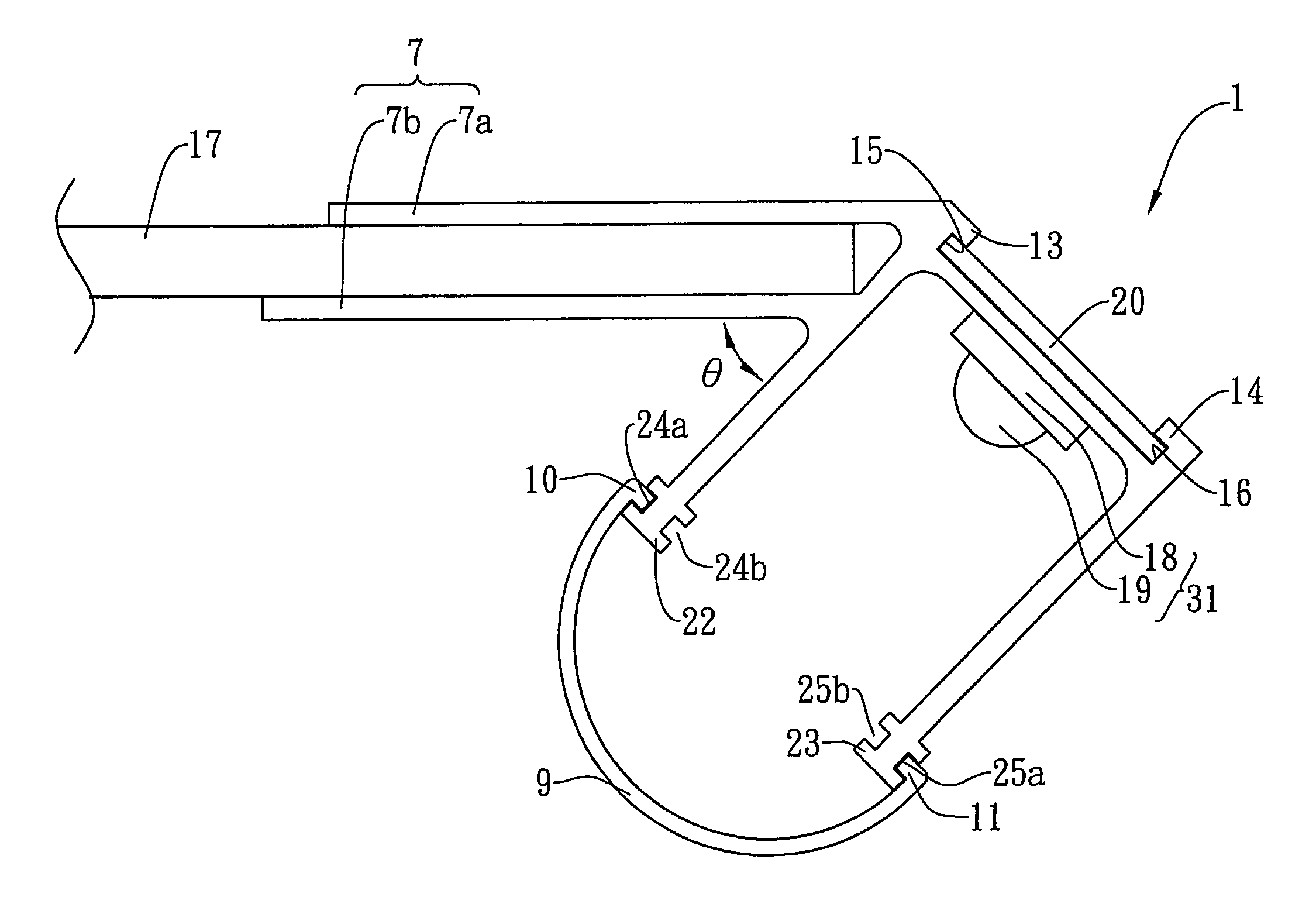
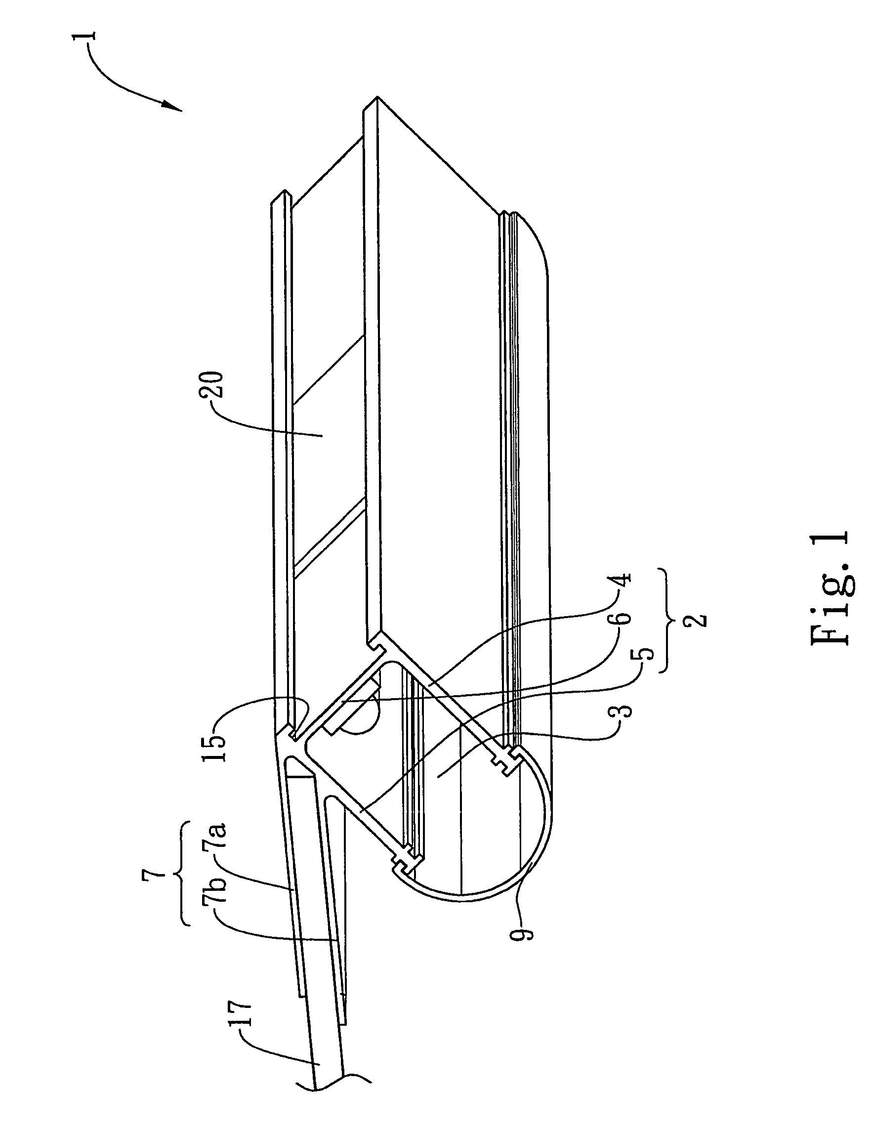
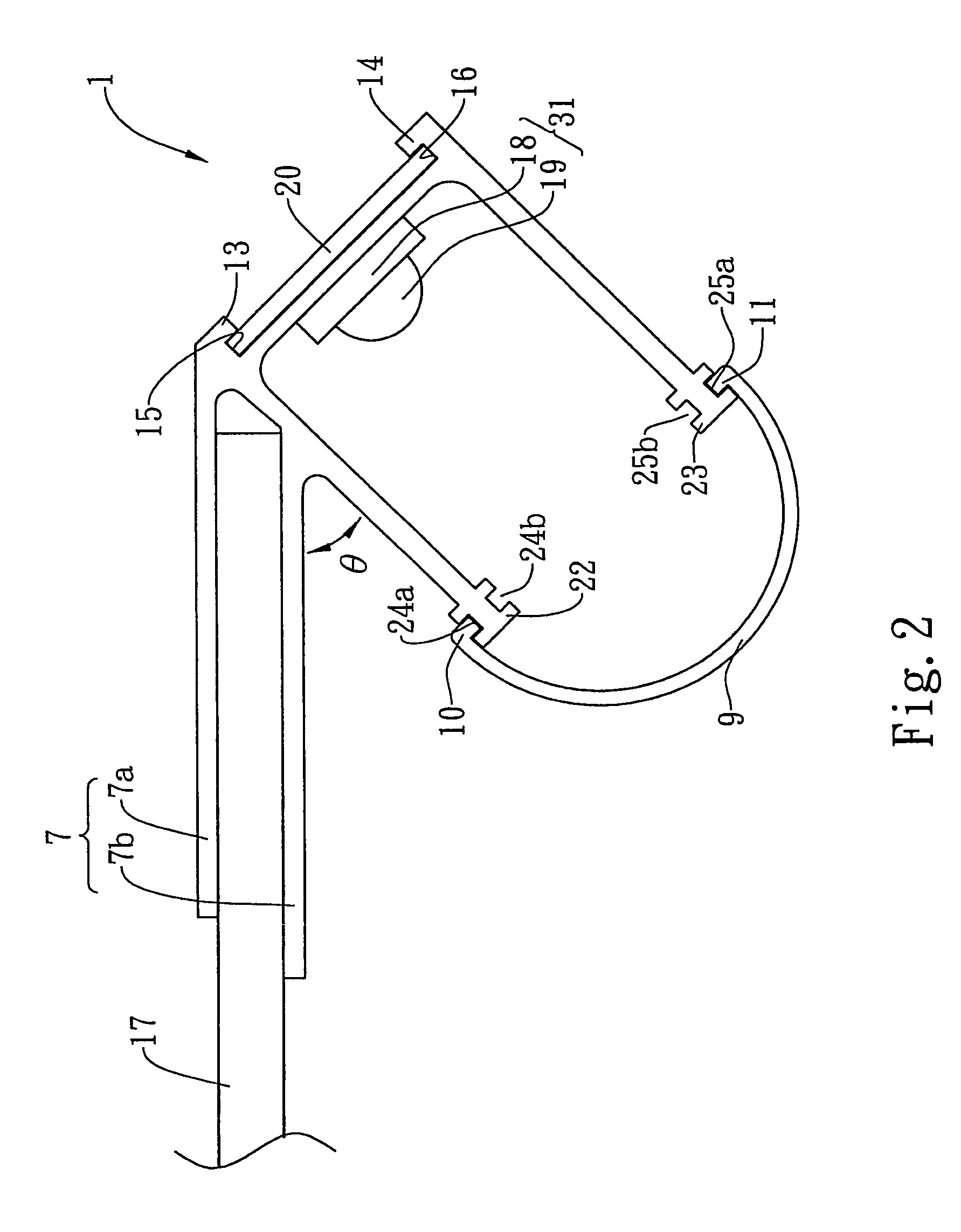
[0025]Please refer to FIGS. 1 and 2 showing the perspective view and side view of the lighting apparatus according to the present invention respectively. The lighting apparatus 1 of the present invention is installed in a refrigerated display cabinet for lighting the product stored therein, and includes a main frame 2 and a lampshade 9. The main frame 2 is constructed by three frame walls 4, 5 and 6, whereby an interior space 3 for receiving a lighting device, such as a light-emitting diode (LED) assembly 31, is defined. Typically the LED assembly 31 is constructed by a base 18 and an LED 19 thereon, and is attached onto the inner face, i.e. the face toward the interior space, of the frame wall 6. The main frame 2 also includes a heat-dissipating portion 7 extending from one side of the first frame wall 4. According to the present invention, the heat-dissipating portion 7 includes two heat sinks 7a and 7b, and is integrated with the main frame 2. The integrated main frame 2, includi...

second embodiment

[0028]FIG. 3 illustrates a lighting apparatus according to the present invention. The construction of the lighting apparatus 21 is similar to that of the lighting apparatus 1 of FIG. 1, except for the following difference. In this embodiment, the LED assembly 30, including the base 27 and LED 28, is not attached on the frame wall 6, but is located within the interior space 3 by the engaging of the substrate 28 with the inner engagement portion, grooves 24b and 25b, of the main frame 2.

[0029]In order to facilitate the thermal dissipation of the lighting apparatus of the present invention, the heat sinks 7a and 7b of the heat-dissipating portion 7 clamping the plate portion 17 of the refrigerated display cabinet is provided with plural grooves 29a or fins 29b formed thereon, as shown in FIG. 4. The dissipation efficiency is significantly enhanced due to the increasing of surface area of the heat sinks 7a and 7b.

[0030]With reference to FIG. 5, the lighting apparatus according to a sec...


PUM


Abstract

The present invention provides an integrated lighting apparatus including a main frame constructed by at least a first frame wall, a second frame wall adjacent to the first frame wall and a third frame wall adjacent to the second frame wall and opposite to the first frame wall. The first, second and third frame walls define an interior space for receiving a lighting device therein. The main frame is integrated with a heat-dissipating portion extending from a first side of the first frame wall. The interior space is covered with the lampshade. Through the heat-dissipating portion, the lighting apparatus is detachably combined with the refrigerated display cabinet in a simple and convenient manner.

Description

BACKGROUND OF THE INVENTION[0001]1. Field of the Invention[0002]The present invention relates to a lighting apparatus, and more particularly, to a lighting apparatus for use with a refrigerated display cabinet.[0003]2. Description of the Related Art[0004]Lights installed in a refrigerated display cabinet are used for illuminating merchandise, so that the products stored therein are well displayed and then sold to customers. Generally, the lights are installed underneath the front end of a cabinet shelf plate portion. In this case, the customers can have a clear view of the products illuminated. Today, lights for use with refrigerated display cabinets are mostly fluorescent lamps, which radiate light in 360 degrees, and as many experimental results show, fluorescent lamps have a power consumption of about 40 W and a luminous efficiency between 40% and 65%. Such results indicate that rather than being effectively transmitted to the products requiring illumination, much of the light is...

Claims


Application Information

Patent Timeline
Patent Type & Authority Patents(United States)
IPC IPC(8): F25D27/00F21V29/00
CPCA47F3/001F21V29/89F21V21/088F21V29/004F21V33/0012G09F3/204G09F13/02F21V29/713F21V29/76A47F3/0482F21S4/003F21V15/013F21W2131/305F21W2131/405F21Y2101/02F21S4/20F21Y2115/10
Inventor HUANG, CHUAN TIMLI, HUNG CHUNYAU, YEU TORNGLEE, LI LING
Owner IND TECH RES INST
Why Eureka
Try Eureka