Stent having less invasive ends and improved radial force

a radial force and endoscope technology, applied in the field of stents for use in body vessels, can solve the problems of relative acute or pointed apices, abraded graft material, breakdown of graft material, leakage through, etc., and achieves less invasiveness, increased conformance to the vessel wall, and increased radial force

Active Publication Date: 2012-03-06
COOK MEDICAL TECH LLC
View PDF34 Cites 15 Cited by
  • Summary
  • Abstract
  • Description
  • Claims
  • Application Information

AI Technical Summary

Benefits of technology

[0012]Advantageously, such a stent is less invasive upon a vessel wall when deployed, and also yields an increased conformance to the vessel wall. Further, the design of a stent having the multiple curved portions described herein yields a significantly increased radial force upon the vessel wall. Moreover, if used in conjunction with a stent-graft, the significantly large radius of curvature yields an increased suture attachment zone, thereby allowing for the provision of a greater number of sutures and enhanced coupling between the stent and the graft.
[0024]In one embodiment, the stent comprises a series of proximal apices disposed at a proximal end of the stent, a series of distal apices disposed at a distal end of the stent, and at least one angled strut segment disposed between the proximal and distal apices of the stent. At least one apex of the stent may comprise multiple curved portions. In one example, the radius of curvature of one of the curved portions of an individual apex is significantly greater than each of the other radii of curvature of the apex. Accordingly, good conformability can be achieved which makes this stent especially suitable for stent graft sealing purposes. The smaller radii of curvature give the stent larger radial force than conventional designs. For example, the radius of curvature of one curved portion may be at least 10 times greater than all other curved portions. The curved portion having the significantly greater radius of curvature may be configured to engage a vessel wall in a less invasive manner.
[0026]In one particular embodiment, each apex of the stent comprises five curved portions. A first angled strut segment transitions into the first curved portion of the apex, and the first curved portion transitions into the second, third, fourth and fifth curved portions of the apex, respectively. The fifth curved portion of the apex then transitions into a second angled strut segment. The first and second angled strut segments may be disposed at an angle of about 70 to 110 degrees relative to each other in an expanded state, thereby facilitating radial expansion of the stent.
[0028]At least one of the angled strut segments may be curved. This enables the stent to provide a more uniform sealing pressure across the whole stent. There is a more uniform contact pressure between the stent and the vessel wall including at the apices of the stent.
[0031]Advantageously, a stent designed in accordance with the examples described herein is less invasive upon a vessel wall when deployed, and also yields an increased conformance to the vessel wall. Further, the design of a stent having the multiple curved portions described herein yields a significantly increased radial force upon the vessel wall. Moreover, if used in conjunction with a stent-graft, the significantly large radius of curvature yields an increased suture attachment zone, thereby allowing for the provision of a greater number of sutures and enhanced coupling between the stent and the graft.

Problems solved by technology

Although having this advantage, in some situations, such relatively acute or pointed apices may be undesirable.
If the acute bends of the apices that engage the graft material are too pointed, sharp or otherwise invasive, then it may adversely impact or abrade the graft material, leading to breakdown of, or leakage through, the graft material.
Similarly, if the ends of the stent that engage the vessel wall are too pointed, sharp or otherwise invasive, then it may have an adverse effect upon the vessel wall in the expanded state.
However, such well-rounded stents may provide a relatively low radial force and may not provide an adequate sealing force upon a vessel wall.

Method used


Image

  • Stent having less invasive ends and improved radial force
  • Stent having less invasive ends and improved radial force
  • Stent having less invasive ends and improved radial force

Examples


Embodiment Construction

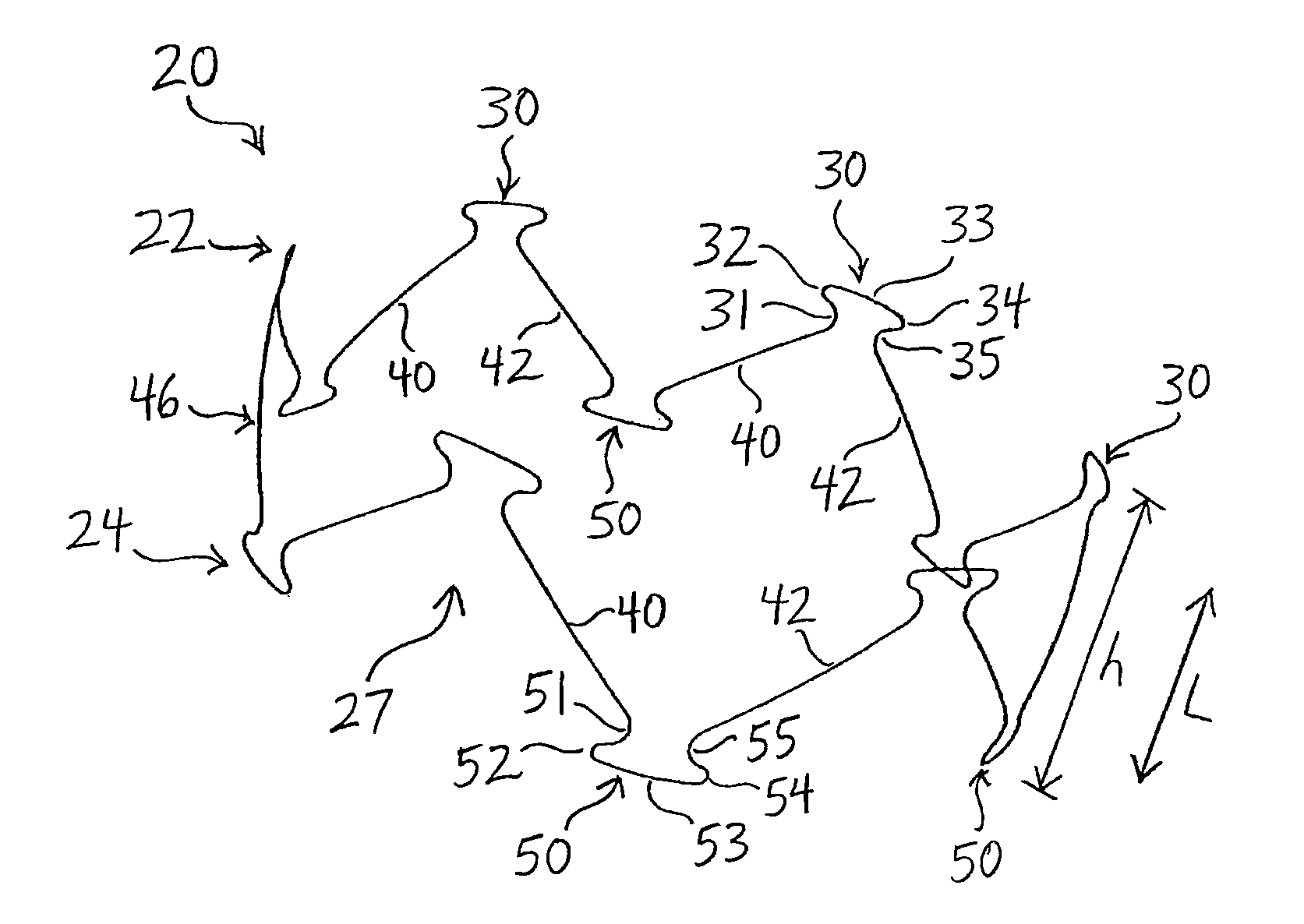
[0041]In the present application, the term “proximal” refers to a direction that is generally closest to the heart during a medical procedure, while the term “distal” refers to a direction that is furthest from the heart during a medical procedure.

[0042]Referring now to FIG. 1, a stent 20 provided in accordance with a first example is described. The stent 20 generally comprises a proximal end 22 and a distal end 24. The stent 20 has a reduced diameter delivery state so that it may be advanced to a target location within a vessel or duct. The stent 20 also has an expanded deployed state, shown in FIG. 1, in which the stent 20 is configured to apply a radially outward force upon at least a portion of a vessel or duct, e.g., to maintain patency within a passageway, or to hold open the lumen of a graft. In the expanded state, fluid flow is allowed through a central lumen 27 of the stent 20.

[0043]As shown in FIG. 1, the proximal end 22 of the stent 20 may comprise multiple adjacent proxi...


PUM


Abstract

The present invention provides a stent having less invasive ends and improved radial force. In one embodiment, the stent comprises a series of proximal apices disposed at a proximal end of the stent, a series of distal apices disposed at a distal end of the stent, and at least one angled strut segment disposed between the proximal and distal apices of the stent. At least one apex of the stent may comprise multiple curved portions. In one example, the radius of curvature of one of the curved portions is significantly greater, for example, at least 10 times greater, than each of the other radii of curvature of the apex. The curved portion having the significantly greater radius of curvature may be configured to engage a vessel wall in a less invasive manner.

Description

RELATED APPLICATIONS[0001]The present patent document is a §371 filing based on PCT Application Ser. No. PCT / US2009 / 004940, filed Sep. 2 , 2009 (and published as WO 2010 / 027450A1 on Mar. 11, 2010), designating the United States and published in English, which claims the benefit of the filing date under 35 U.S.C. §119(e) of Provisional U.S. Patent Application Ser. No. 61 / 093,624, filed Sep. 2 , 2008. All of the foregoing applications are hereby incorporated by reference in their entirety.TECHNICAL FIELD[0002]The present invention relates generally to apparatus and methods for treating medical conditions, and more specifically, to stents for use in body vessels to treat those medical conditions.BACKGROUND ART[0003]Stents may be inserted into an anatomical vessel or duct for various purposes. Stents may maintain or restore patency in a formerly blocked or constricted passageway, for example, following a balloon angioplasty procedure. Other stents may be used for different procedures, f...

Claims


Application Information

Patent Timeline
Patent Type & Authority Patents(United States)
IPC IPC(8): A61F2/82A61F2/90
CPCA61F2/90A61F2/07A61F2230/0054A61F2220/0075A61F2220/0016
Inventor LEEWOOD, ALAN R.YANG, SHUO
Owner COOK MEDICAL TECH LLC
Why Eureka
Try Eureka