
System and method for harvesting energy from environmental vibrations

a technology of environmental vibration and energy harvesting, applied in piezoelectric/electrostrictive/magnetostrictive devices, piezoelectric/electrostriction/magnetostriction machines, electrical apparatus, etc., can solve the problems of low durability of batteries, frequent replacement, and high cost of procedures, so as to increase the harvesting power, the effect of adequate vibration levels and less power

Active Publication Date: 2012-03-06
UNIVERSITY OF MISSOURI
View PDF3 Cites 4 Cited by
  • Summary
  • Abstract
  • Description
  • Claims
  • Application Information

AI Technical Summary

Benefits of technology

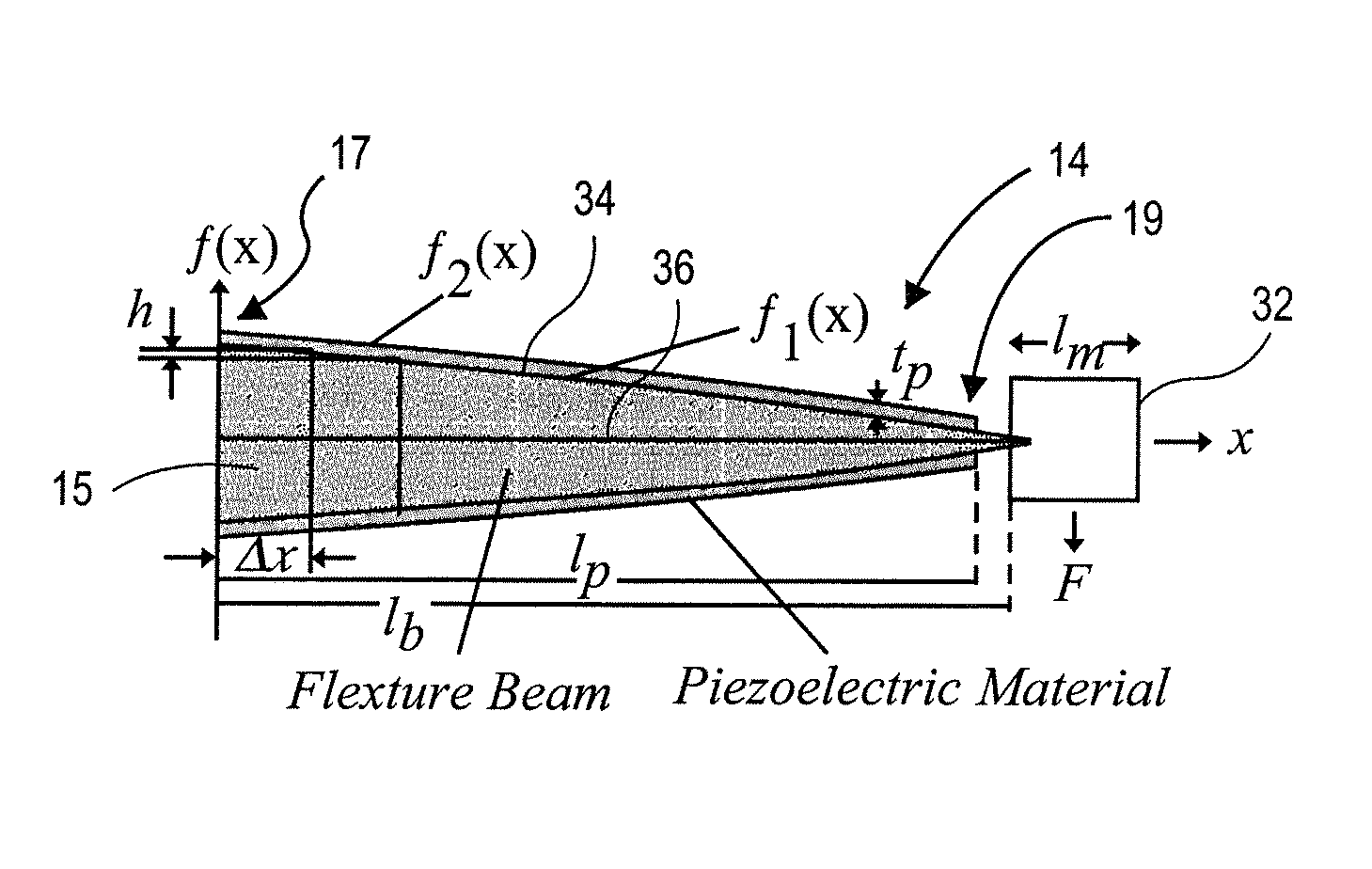
[0013]The tapered cantilever beam of embodiments of the present invention has the advantage of a more uniform distribution of strain across the piezoelectric element coupled to the beam than prior art beam shapes, such as rectangular or trapezoidal. Applicants' simulations show that the tapered beam of embodiments of the present invention has a nearly constant strain profile and is able to produce almost twice as much average strain on the beam as compared to the rectangular-shaped beam of the prior art.

Problems solved by technology

Batteries are commonly used to power these devices, but due to the batteries' low durability, they must be replaced periodically.
This procedure is costly, especially for devices that are associated with remote structures.
However, in the case of piezoelectric sources, the scavenged energy is often quite small, and thus, the harvested or scavenged energy is only useful either as a supplement to an existing energy source, such as a battery, or to power small electronic devices.
Additionally, the shape of the beam itself, and consequently, the shape of the piezoelectric material coupled to the beam, affects the possible power output.
The shaped voltage waveform in prior art voltage inversion techniques increases the harvested power noticeably; however, the optimal voltage waveform is usually not obtained.

Method used


Image

  • System and method for harvesting energy from environmental vibrations
  • System and method for harvesting energy from environmental vibrations
  • System and method for harvesting energy from environmental vibrations

Examples


examples

[0098]Applicants performed a series of experiments to test the tapered cantilever beam 14 design and the voltage compensating circuit 20 of embodiments of the present invention. The experimental setup comprised two 15 cm steel cantilever beams: a first, prior art rectangular-shaped beam 48 illustrated in FIG. 12, and a second, tapered beam 14 of embodiments of the present invention. Both beams 14,48 were fixed on a shaker (i.e., the vibration-producing device 12). The beams 14,48 were monitored at thirty-two equally spaced points along the beam, beginning with ƒ1(x)=2 mm at the fixed end using Equation (11). The piezoelectric elements 16 used were thin, flexible strips of composite fibers with laminate coating that were glued on the beams using epoxy. The material specifications for the piezoelectric element 16 are shown in the below Table 1:

[0099]

TABLE 1Piezoelectric Element Specifications(Advanced Cerametrics Inc.)SpecificationsValuesFiber TypePZT_5ADimensions13.0 cm × 1.0 cm × 0....


PUM


Abstract

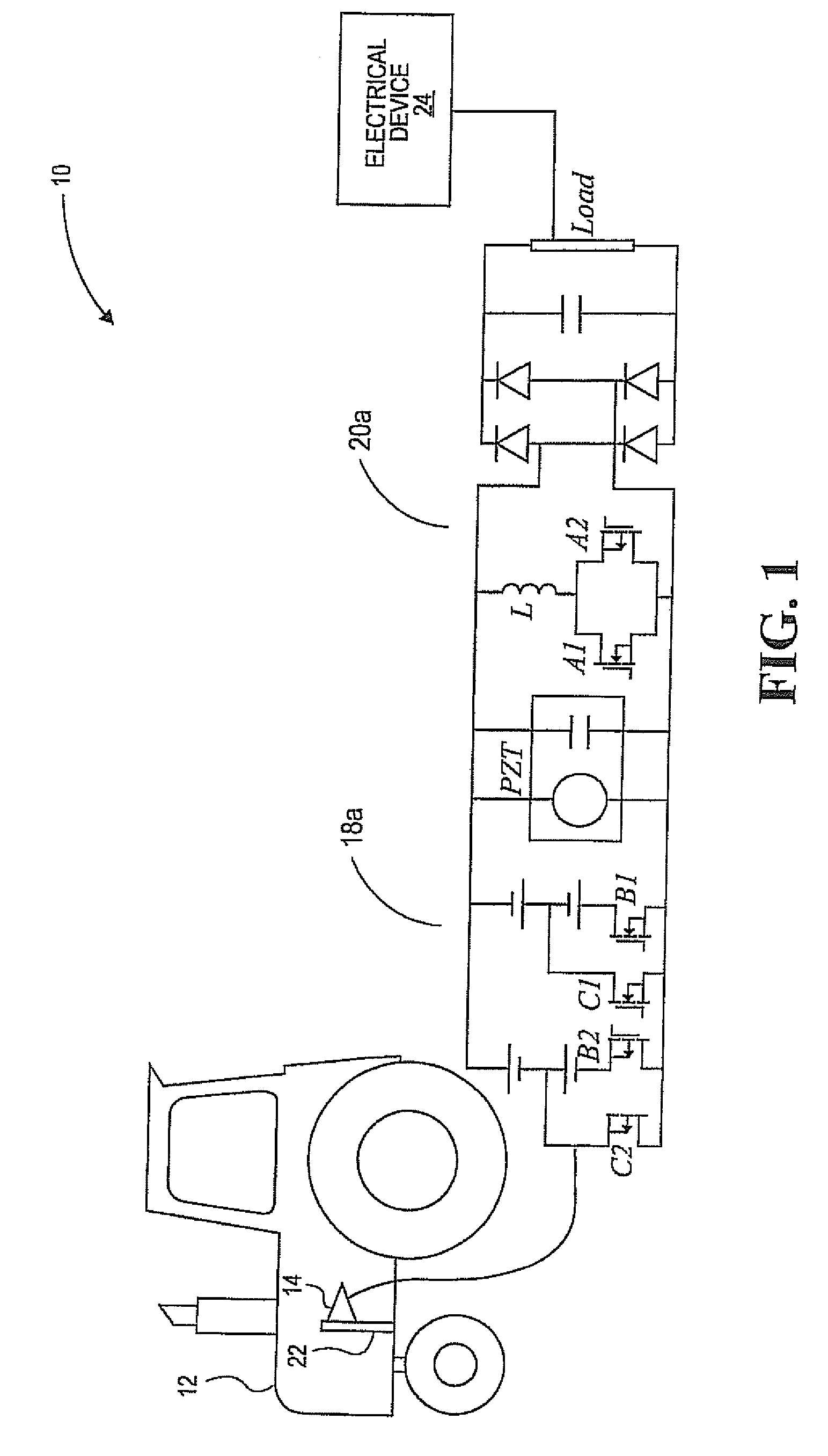
Embodiments of the present invention provide a system and a method for increasing the harvested energy from a piezoelectric element exposed to environmental vibrations via a two-prong system. In a first prong, a cantilever beam is tapered and shaped so as to increase and provide an approximately uniform strain on and along the beam, thus resulting in increased voltage. In a second prong of the system and method, a voltage compensating circuit, when used with a voltage inversion circuit of the prior art, increases the harvested power by injecting current to the piezoelectric element after each voltage inversion so as to increase the voltage level.

Description

FEDERALLY SPONSORED RESEARCH / DEVELOPMENT PROGRAM[0001]This invention was made with government support under contract number IIP-0639182 awarded by the National Science Foundation. The United States government has certain rights in the invention.BACKGROUND[0002]1. Field[0003]The present invention relates to a system and method for harvesting energy from environmental vibrations. More particularly, embodiments of the present invention relate to a system and method for harvesting energy by applying mechanical strain to a specially-shaped piezoelectric element and harvesting the resulting output power using a combination of a voltage inversion circuit, a voltage compensating circuit, and the specially-shape piezoelectric element.[0004]2. Description of the Related Art[0005]Wireless sensors and other portable electronic devices are becoming ubiquitous. Batteries are commonly used to power these devices, but due to the batteries' low durability, they must be replaced periodically. This pr...

Claims


Application Information

Patent Timeline
Patent Type & Authority Patents(United States)
IPC IPC(8): H01L41/08
CPCH01L41/1136H02N2/181H02N2/186H10N30/306
Inventor MEHRAEEN, SHAHABSARANGAPANI, JAGANNATHAN
Owner UNIVERSITY OF MISSOURI
Learn More