Method of production rare-earth magnet

a rare earth magnet and production method technology, applied in the direction of magnetic materials, inductance/transformer/magnet manufacturing, magnetic bodies, etc., can solve the problems of plastic deformation, significant non-uniform strain distribution in the sectional direction of the magnet, and non-uniform strain distribution of the magnet, etc., to suppress deformation, uniform strain distribution, and suppress deformation

Active Publication Date: 2017-12-19
TOYOTA JIDOSHA KK
View PDF3 Cites 0 Cited by
  • Summary
  • Abstract
  • Description
  • Claims
  • Application Information

AI Technical Summary

Benefits of technology

[0017]The invention relates to a method of producing a rare-earth magnet through hot working, and provides the method of producing a rare-earth magnet, which improves residual magnetization by making strain distribution uniform.
[0023]The frictional force in the lateral direction, which acts on the upper and lower surfaces of the sintered body, is largest at the central portions of the upper and lower surfaces of the sintered body, and decreases toward both side surfaces of the sintered body, which are in the unconstrained state. The frictional force acts to hinder the plastic flow of the sintered body in the lateral direction. Accordingly, the plastic flow is less likely to occur (i.e., the ease, with which the plastic flow occurs, decreases) toward the central portion of the sintered body from both side surfaces of the sintered body, which are in the unconstrained state.
[0024]With regard to the sintered body pressing direction, an effect of the frictional force on the plastic flow of the sintered body decreases toward the internal center of the sintered body, that is, an intermediate portion between the upper and lower surfaces from the constrained upper and lower surfaces of the sintered body. Accordingly, the plastic flow of the sintered body is more likely to occur (i.e., the ease, with which the plastic flow of the sintered body occurs, increases) toward the internal center of the sintered body from the constrained upper and lower surfaces of the sintered body.
[0039]Thus, the plastic flow of the sintered body and the rare-earth magnet precursor becomes more uniform through the first hot working and the second hot working, as compared to the related art, and thus the strain distribution in the section of the rare-earth magnet is more uniform, as compared to the related art. As described, since the strain of the produced rare-earth magnet is uniform, magnetic properties in the vicinity of a surface of the rare-earth magnet are improved, and the overall magnetic properties are improved. As a result, a low-magnetization portion of the rare-earth magnet decreases, and thus a yield ratio of the rare-earth magnet is also improved.
[0043]When each of the sintered body and the rare-earth magnet precursor is further pressed, each of the sintered body and the rare-earth magnet precursor is further plastically deformed, and thus the side surface, which is to be brought to the constrained state, comes into contact with the die and the side surface is brought to the constrained state. In each of the sintered body and the rare-earth magnet precursor, after the side surface comes into contact with the die, the region in which the plastic flow is most unlikely to occur is present in the vicinity of the side surface that is brought to the constrained state. Thus, in each of the sintered body and the rare-earth magnet precursor, the region, in which the plastic flow is most unlikely to occur, is changed in the course of the pressing. This change also contributes to making the strain distribution of the rare-earth magnet uniform.
[0045]As can be seen from the above description, according to the method of producing a rare-earth magnet according to the above-mentioned aspect of the invention, the rare-earth magnet precursor is produced by the first hot working in which, in the two side surfaces of the sintered body, which are parallel to the pressing direction and are opposite to each other, one side surface is brought to the constrained state to suppress deformation, and the other side surface is brought to the unconstrained state to permit deformation. In addition, the rare-earth magnet is produced by the second hot working in which, in the two side surfaces of the rare-earth magnet precursor, which are parallel to the pressing direction, a side surface, which is in the unconstrained state in the first hot working, is brought to the constrained state to suppress deformation, and a side surface, which is in the constrained state in the first hot working, is brought to the unconstrained state to permit deformation. Accordingly, it is possible to make the strain distribution uniform while giving desired magnetic anisotropy to the rare-earth magnet. As a result, it is possible to produce the rare-earth magnet, which is excellent in magnetic properties in the vicinity of a surface and the overall magnetic properties, with a high yield ratio.

Problems solved by technology

As a result, plastic deformation occurs.
As a result, a difference in a strain amount in a lateral direction and a pressing direction is caused in the sintered body due to a difference in material flowability, and thus a strain distribution of a magnet becomes non-uniform in a section of the sintered body, which is parallel to the pressing direction.
As a result, for example, when strong working in which the compression rate of the sintered body is approximately 10% or higher is performed, the strain distribution in a sectional direction of the magnet becomes significantly non-uniform.
Therefore, in a case where a plate material obtained by the rolling is a plate material having a predetermined length, and the plate material is not a continuous band plate, there is a possibility that the non-uniform strain distribution as described above may occur in a section along the longitudinal direction of the plate material.
As described above, in the technologies disclosed in JP 4-134804 A and JP 2-250922 A, it may not be possible to prevent occurrence of the non-uniform strain distribution when the rare-earth magnet is produced through the hot working.

Method used


Image

  • Method of production rare-earth magnet
  • Method of production rare-earth magnet
  • Method of production rare-earth magnet

Examples


first embodiment

of Method of Producing Rare-Earth Magnet

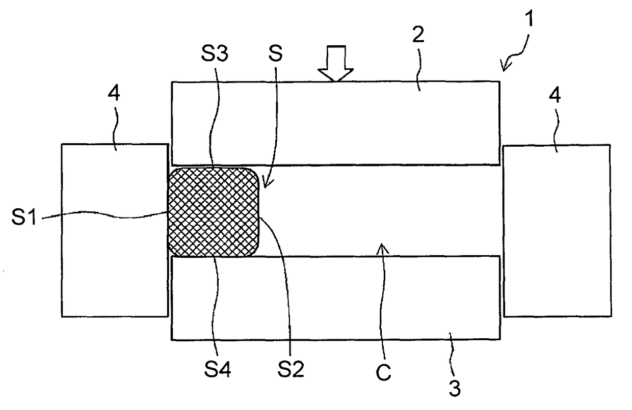
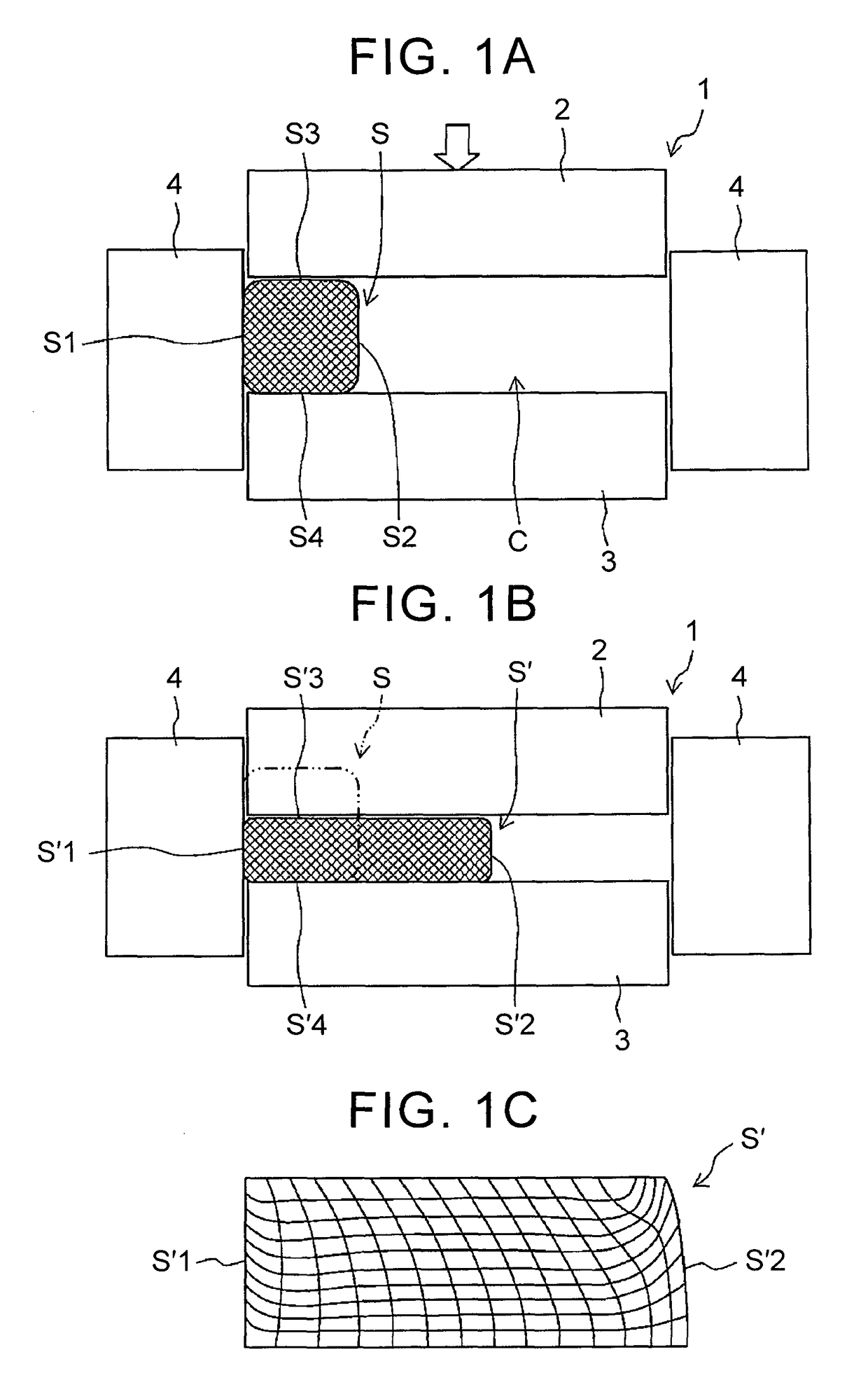
[0057]In a method of producing a rare-earth magnet according to this embodiment, a sintered body, which is solidified by sintering a rare-earth magnet material such as a magnet powder produced by, for example, a liquid quenching method, is subjected to hot working to obtain a desired shape, and to give magnetic anisotropy to the sintered body.

[0058]In this embodiment, for example, the sintered body which is subjected to the hot working is produced as follows. First, an alloy ingot is high-frequency melted in a furnace (not shown) under an Ar gas atmosphere decompressed to, for example, 50 kPa or lower according to a melt spinning method using a single roll, and a molten metal having a composition for producing a rare-earth magnet is sprayed onto a copper roll to prepare a quenched thin band (a quenched ribbon), and this quenched ribbon is coarsely crushed.

[0059]Next, the quenched ribbon that is coarsely crushed is filled in a cavity defined by...

second embodiment

of Method of Producing Rare-Earth Magnet

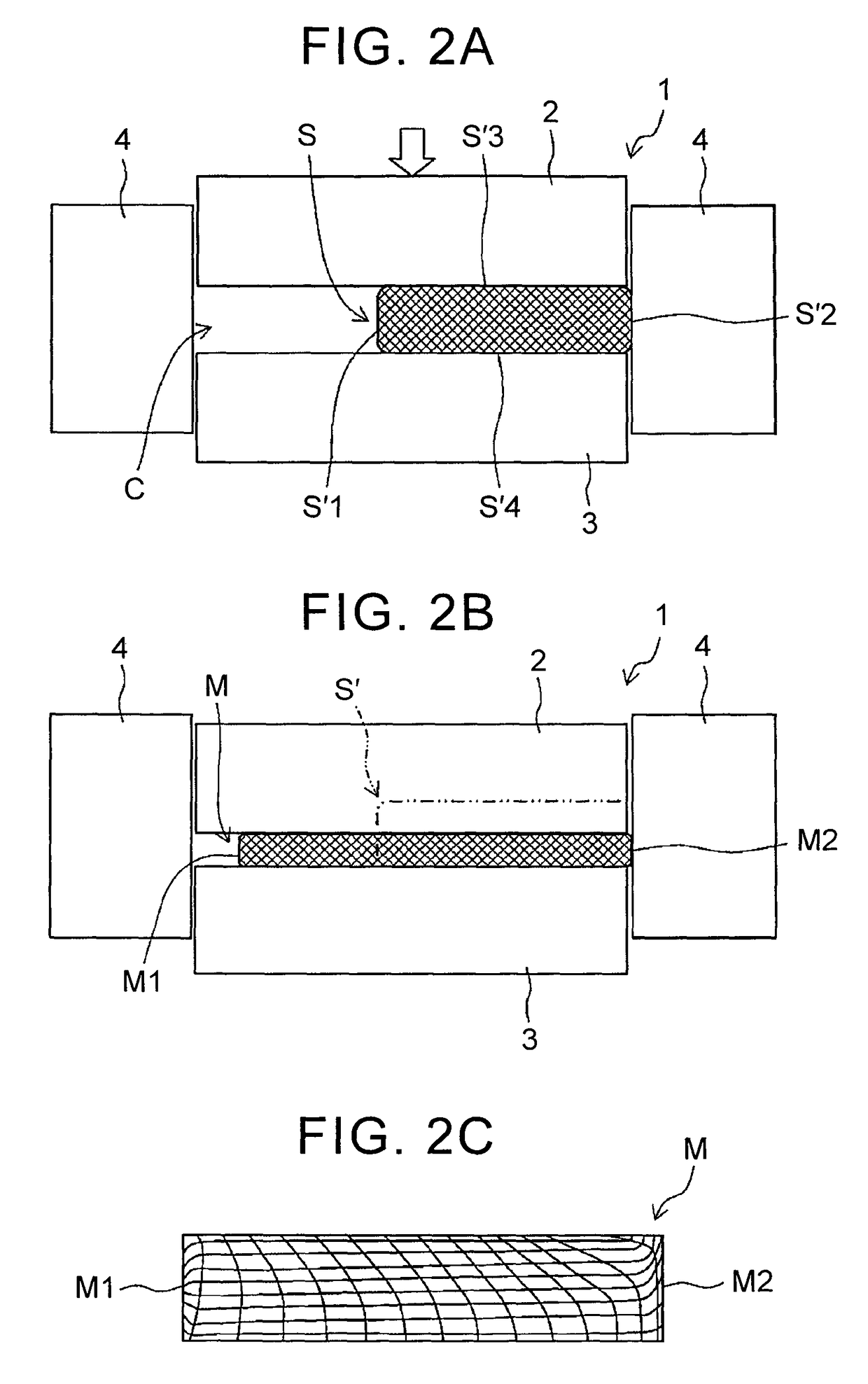
[0082]Hereinafter, a method of producing the rare-earth magnet according to a second embodiment of the invention will be described with reference to the attached drawings. The method of producing the rare-earth magnet according to this embodiment is different from the first embodiment in that side surfaces of the sintered body and the rare-earth magnet precursor, which are to be brought to the constrained state, are not caused to come into contact with the inner surface of the die and are brought to the unconstrained state at an initial stage of the pressing, and are caused to come into contact with the inner surface of the die and are brought to the constrained state in the course of the pressing. The other configurations are the same as the first embodiment, and the same reference numerals are given to the same configurations and a description thereof will not be repeated.

[0083]FIGS. 3A to 3C are process diagrams of a first step of this embo...


PUM

PropertyMeasurementUnit
temperatureaaaaaaaaaa

Abstract

A production method includes producing a rare-earth magnet precursor (S′) by performing first hot working in which, in two side surfaces of a sintered body, which are parallel to a pressing direction and are opposite to each other, one side surface is brought to a constrained state to suppress deformation, and the other side surface is brought to an unconstrained state to permit deformation; and producing a rare-earth magnet by performing second hot working in which, in two side surfaces (S′1, S′2) of the rare-earth magnet precursor (S′), which are parallel to the pressing direction, a side surface (S′2), which is in the unconstrained state in the first hot working, is brought to the constrained state to suppress deformation, and a side surface (S′1), which is in the constrained state in the first hot working, is brought to the unconstrained state to permit deformation.

Description

BACKGROUND OF THE INVENTION[0001]1. Field of the Invention[0002]The invention relates to a method of producing a rare-earth magnet that is an oriented magnet, by hot working.[0003]2. Description of Related Art[0004]A rare-earth magnet using a rare-earth element such as lanthanoid is also called a permanent magnet. The rare-earth magnet has been used for a drive motor of a hybrid car or an electric vehicle in addition to a hard disk and a motor that constitutes an MRI.[0005]As an index of a magnetic performance of the rare-earth magnet, residual magnetization (a residual magnetic flux density) and a coercive force may be exemplified. With an increase in amount of heat generation due to reduction of the size of a motor or an increase in the current density of a motor, demand for heat resistance of the used rare-earth magnet is further increasing. Accordingly, maintaining the magnetic properties of the magnet when the magnet is used under high-temperature is important.[0006]Here, an ex...

Claims


Application Information

Patent Timeline
Patent Type & Authority Patents(United States)
IPC IPC(8): C22C33/02H01F1/057C21D6/00C21D8/00C21D8/12C22C38/00C22C38/10B22F3/02H01F41/02
CPCH01F41/0266C21D6/007C21D8/005C21D8/1211H01F1/0577C22C38/002C22C38/005C22C38/10H01F1/0576C21D8/1216
Inventor KANO, AKIRAKOBUCHI, DAIHOSHINA, EISUKEYAMASHITA, OSAMUMIYAMOTO, NORITAKA
Owner TOYOTA JIDOSHA KK
Why Eureka
Try Eureka