Production method for rare earth permanent magnet

a production method and permanent magnet technology, applied in the direction of magnetic materials, electrophoretic coatings, magnetic bodies, etc., can solve the problems of unavoidable loss of remanence, permanent magnets within the rotary machine exposed to elevated temperature, and the above method suffers from some problems, so as to achieve high remanence

Active Publication Date: 2015-07-30
SHIN ETSU CHEM IND CO LTD
View PDF6 Cites 20 Cited by
  • Summary
  • Abstract
  • Description
  • Claims
  • Application Information

AI Technical Summary

Benefits of technology

[0022]The method of the invention ensures that a R—Fe—B base sintered magnet having a high remanence and coercive force is prepared in an efficient manner.

Problems solved by technology

The permanent magnets within the rotary machine are exposed to elevated temperature due to the heat generation of windings and iron cores and kept susceptible to demagnetization by a diamagnetic field from the windings.
Therefore, as long as the above approach is taken to increase coercive force, a loss of remanence is unavoidable.
The above method, however, suffers from some problems.
Lowering the sintering temperature is effective to minimize the excessive diffusion into crystal grains, but not practically acceptable because low temperatures retard densification by sintering.
An alternative approach of sintering a compact at low temperature under a pressure applied by a hot press or the like is successful in densification, but entails an extreme drop of productivity.
However, the application of metal coating by sputtering poses the problem of low productivity.
The immersion and spraying methods are difficult to control the coating weight (or coverage) of powder.
A short coverage fails in sufficient absorption of R2.
Inversely, if an extra amount of powder is coated, precious R2 is consumed in vain.
Furthermore, since a powder coating is not so adherent, problems are left including poor working efficiency of the process from the coating step to the heat treatment step and difficult treatment over a large surface area.

Method used


Image

  • Production method for rare earth permanent magnet
  • Production method for rare earth permanent magnet
  • Production method for rare earth permanent magnet

Examples


example 1

[0055]An alloy in thin plate form was prepared by a strip casting technique, specifically by weighing Nd, Al, Fe and Cu metals having a purity of at least 99% by weight, Si having a purity of 99.99% by weight, and ferroboron, high-frequency heating in an argon atmosphere for melting, and casting the alloy melt on a copper single roll. The alloy consisted of 14.5 atom % of Nd, 0.2 atom % of Cu, 6.2 atom % of B, 1.0 atom % of Al, 1.0 atom % of Si, and the balance of Fe. Hydrogen decrepitation was carried out by exposing the alloy to 0.11 MPa of hydrogen at room temperature to occlude hydrogen and then heating at 500° C. for partial dehydriding while evacuating to vacuum. The decrepitated alloy was cooled and sieved, yielding a coarse powder under 50 mesh.

[0056]Subsequently, the coarse powder was finely pulverized on a jet mill using high-pressure nitrogen gas into a fine powder having a mass median particle diameter of 5 μm. The fine powder was compacted in a nitrogen atmosphere under...

reference example 1

[0067]An alloy in thin plate form was prepared by a strip casting technique, specifically by weighing Nd, Al, Fe and Cu metals having a purity of at least 99% by weight, Si having a purity of 99.99% by weight, and ferroboron, high-frequency heating in an argon atmosphere for melting, and casting the alloy melt on a copper single roll. The alloy consisted of 14.5 atom % of Nd, 0.2 atom % of Cu, 6.2 atom % of B, 1.0 atom % of Al, 1.0 atom % of Si, and the balance of Fe. Hydrogen decrepitation was carried out by exposing the alloy to 0.11 MPa of hydrogen at room temperature to occlude hydrogen and then heating at 500° C. for partial dehydriding while evacuating to vacuum. The decrepitated alloy was cooled and sieved, yielding a coarse powder under 50 mesh.

[0068]Subsequently, the coarse powder was finely pulverized on a jet mill using high-pressure nitrogen gas into a fine powder having a mass median particle diameter of 5 μm. The fine powder was compacted in a nitrogen atmosphere under...

reference example 2

[0072]As in Reference Example 1, a magnet body having dimensions of 17 mm×17 mm×2 mm (magnetic anisotropy direction) was prepared.

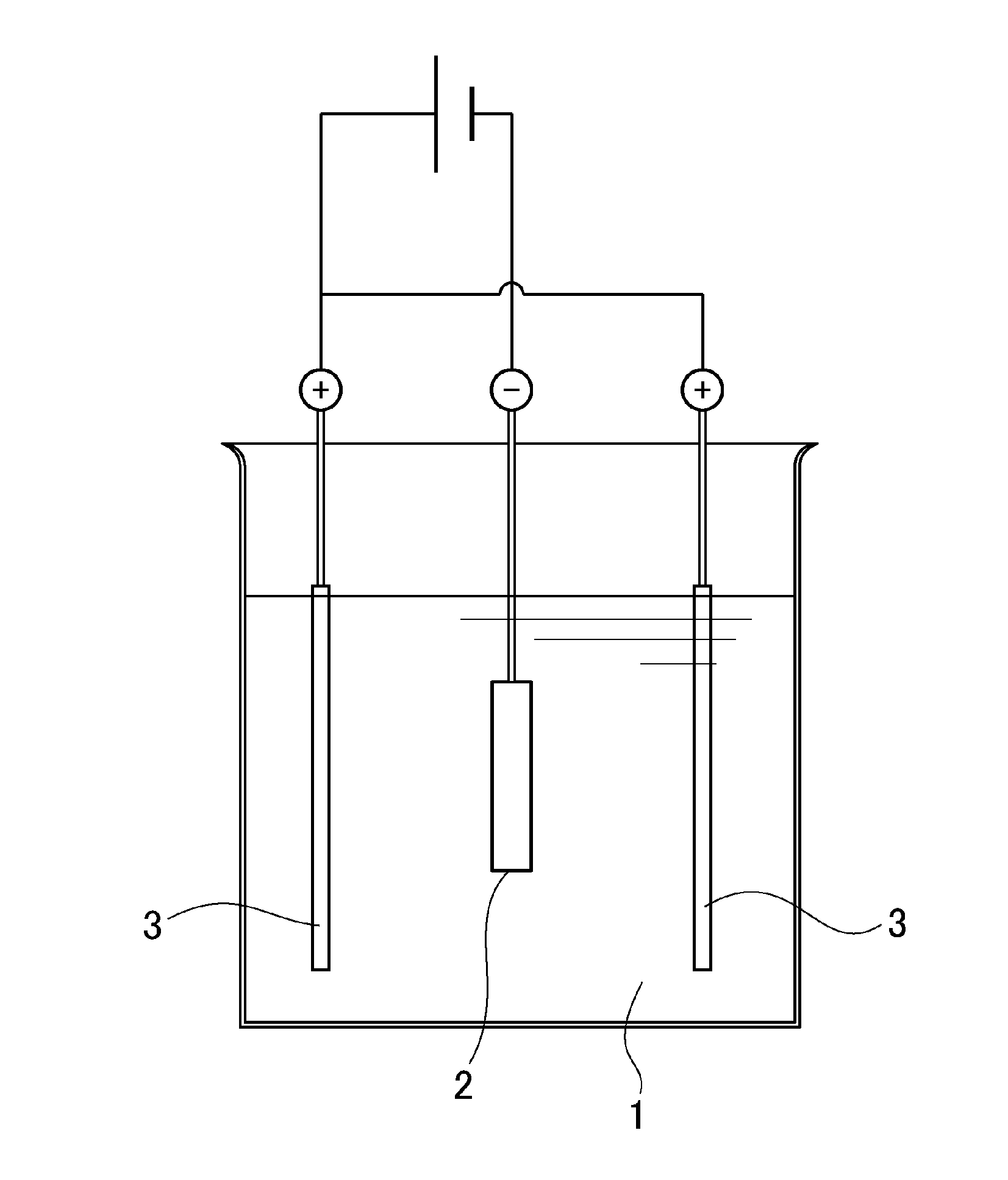
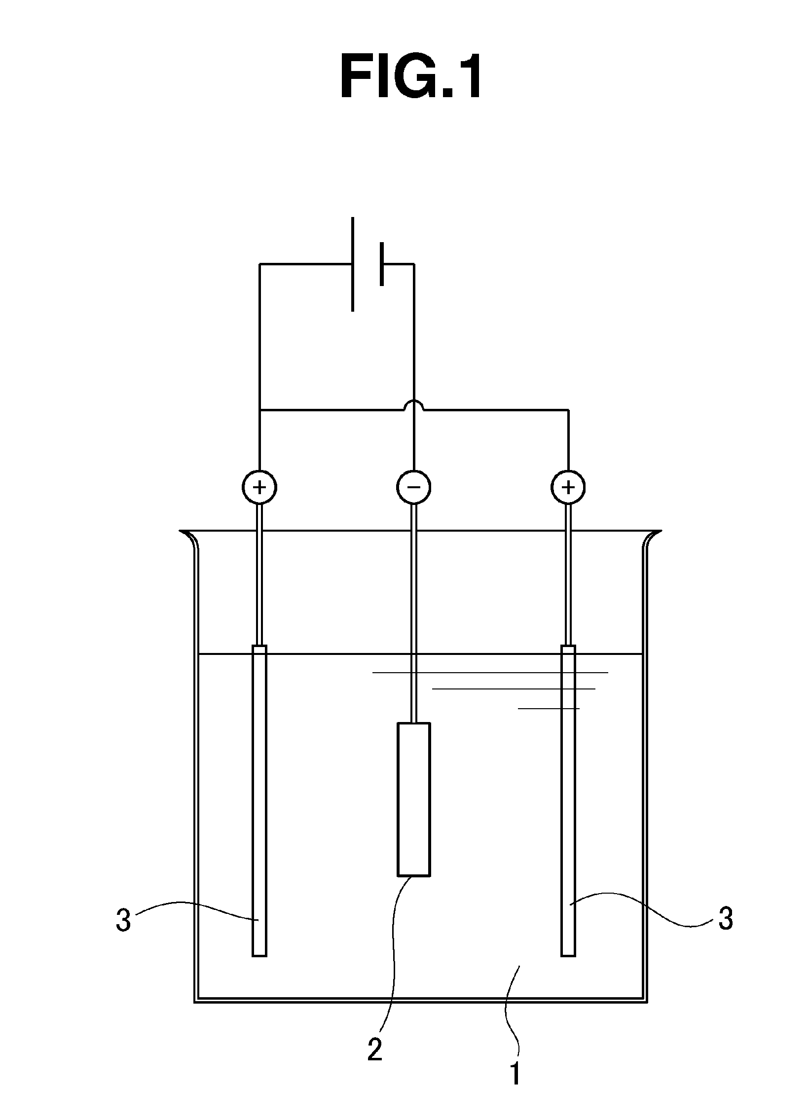
[0073]Also, terbium fluoride (TbF3) having an average particle size of 4 μm was thoroughly mixed with ethanol at a weight fraction of 40% to form a slurry having terbium fluoride particles dispersed therein. The slurry served as an electrodepositing bath.

[0074]Using the slurry, a thin coating of terbium fluoride particles was formed on the magnet body surface as in Reference Example 1. The area density of terbium fluoride deposited was 100 μg / mm2 on the magnet body surface.

[0075]As in Reference Example 1, the coating thickness and coercive force were measured to examine their distribution. The results are reported in Tables 1 and 2. As seen from Tables 1 and 2, the coating thickness was 220 μm at maximum and 130 μm at minimum, and the coercive force was increased by 720 kA / m at maximum and 590 kA / m at minimum.


PUM

PropertyMeasurementUnit
particle sizeaaaaaaaaaa
volume fractionaaaaaaaaaa
sizeaaaaaaaaaa

Abstract

A production method for a rare earth permanent magnet, wherein: a sintered magnet body comprising an R1—Fe—B composition (R1 represents one or more elements selected from among rare earth elements, including Y and Sc) is immersed in an electrodeposition liquid comprising a slurry obtained by dispersing a powder containing an R2 fluoride (R2 represents one or more elements selected from among rare earth elements, including Y and Sc) in water; an electrodeposition process is used to coat the powder onto the surface of the sintered magnet body; and, in the state in which the powder is present on the surface of the magnet body, the magnet body and the powder are subjected to a heat treatment in a vacuum or an inert gas at a temperature equal to or less than the sintering temperature of the magnet.

Description

TECHNICAL FIELD[0001]This invention relates to a method for preparing a R—Fe—B base permanent magnet which is increased in coercive force while suppressing a decline of remanence (or residual magnetic flux density).BACKGROUND ART[0002]By virtue of excellent magnetic properties, Nd—Fe—B base permanent magnets find an ever increasing range of application. In the field of rotary machines such as motors and power generators, permanent magnet rotary machines using Nd—Fe—B base permanent magnets have recently been developed in response to the demands for weight and profile reduction, performance improvement, and energy saving. The permanent magnets within the rotary machine are exposed to elevated temperature due to the heat generation of windings and iron cores and kept susceptible to demagnetization by a diamagnetic field from the windings. There thus exists a need for a sintered Nd—Fe—B base magnet having heat resistance, a certain level of coercive force serving as an index of demagne...

Claims


Application Information

Patent Timeline
Patent Type & Authority Applications(United States)
IPC IPC(8): C25D7/00H01F1/053H01F1/057C21D1/28
CPCC25D7/001H01F1/057H01F1/0536C21D1/28B22F3/24C22C38/002C22C38/005C22C38/02C22C38/06C22C38/14B22F2003/242B22F2003/248C25D13/02C25D13/22H01F1/0577H01F41/0293
Inventor NAGASAKI, YOSHIFUMISHIMAO, MASANOBU
Owner SHIN ETSU CHEM IND CO LTD
Why Eureka
Try Eureka