Transition mode power factor correction device with built-in automatic total harmonic distortion reduction feature

a technology of power factor correction and automatic total harmonic distortion reduction, which is applied in the direction of electric variable regulation, process and machine control, instruments, etc., can solve the problems of low power transmission efficiency, unsatisfactory line voltage shape distortion, and possible interference with other units connected to the power lin

Active Publication Date: 2012-03-06
FREMONT MICRO DEVICES CORP
View PDF3 Cites 17 Cited by
  • Summary
  • Abstract
  • Description
  • Claims
  • Application Information

AI Technical Summary

Benefits of technology

[0025]a RS Flip-Flop Register and a Gate Driver combined to create a required analog waveform pattern for driving the Power Switch and thereby approximating the shape of the current running through the boost inductor to the sinusoidal waveform of the rectified sinusoidal line voltage and in the meantime to keep the valley of the scale-down rectified sinusoidal line voltage close to a reference value.

Problems solved by technology

Injection of high harmonics into the power line is well-known to cause many problems.
Among these are the lower efficiency of power transmission, possible interference to other units connected to the power line, and distortion of the line voltage shape that is undesirable.
A major drawback of the prior art design is the need of manual adjustment on the resistance value of 1R6 to find the optimum solution.

Method used


Image

  • Transition mode power factor correction device with built-in automatic total harmonic distortion reduction feature
  • Transition mode power factor correction device with built-in automatic total harmonic distortion reduction feature
  • Transition mode power factor correction device with built-in automatic total harmonic distortion reduction feature

Examples


Embodiment Construction

[0041]These and other advantage, aspect and novel features of the present invention, as well as details of an illustrated embodiment thereof, will be more fully understand from the following description and drawings. While various embodiments of the present invention has been presented by way of example only, and not limitation.

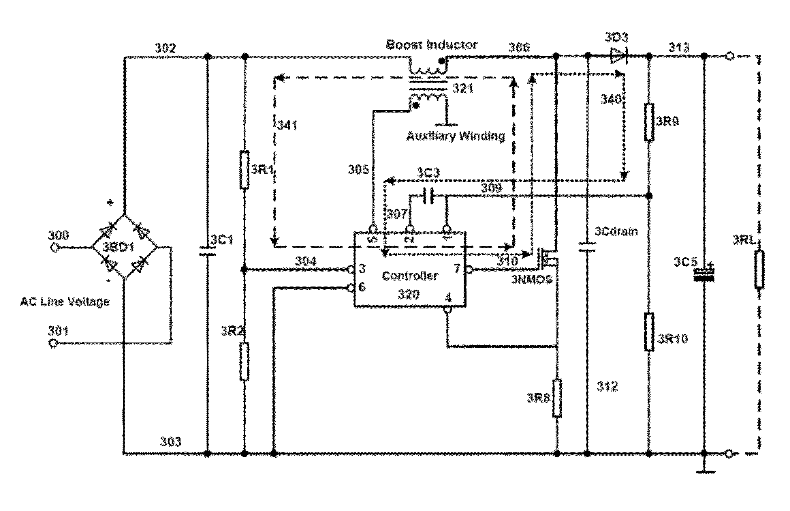
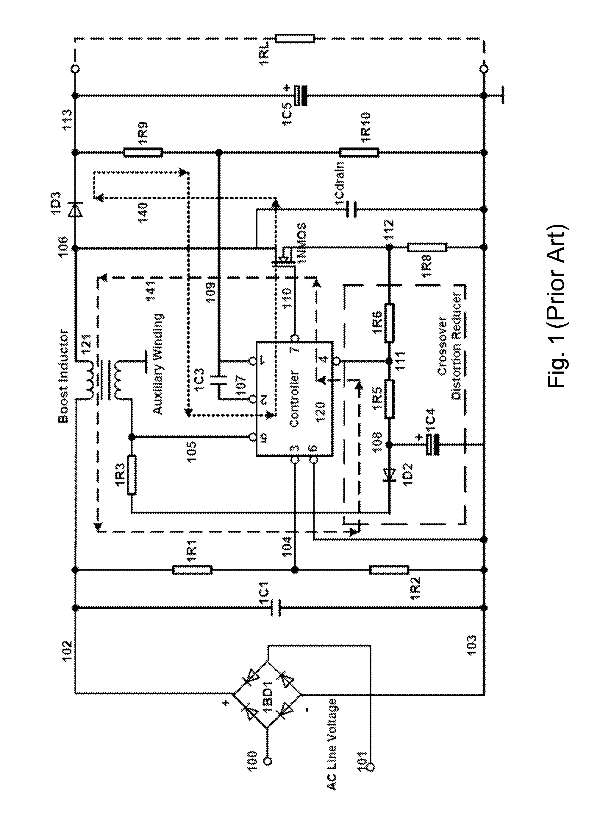
[0042]A device equipped with Auto THD optimization function for the correction of the power factor in AC-DC power converter is proposed. It is an innovative solution for resolving Crossover Distortion problem in Active Power Factor Correction AC-DC Converter System (APFCS) without the need of manual adjustment on CDR resistor value R6 (FIG. 1) for THD optimization like the prior art described in the FIG. 1.

[0043]The built-in Auto THD optimization function enable the system automatically searching for optimum offset voltage for THD optimization in spite of the AC line voltage, output loading and parasitic capacitor capacitance at node 106 or 306. The operation...


PUM


Abstract

A controller for reducing the harmonics contents in the AC-to-DC converter that is capable of minimizing THD due to crossover distortion. The controller can approximate the shape of the current running through boost inductor to the sinusoidal waveform of the rectified line input voltage and in the meantime to keep the valley of rectified sinusoidal waveform line voltage close to local ground value. The controller can be used in a transition mode power factor correction device suitable for a wide range of AC line input voltage and output loading application.

Description

REFERENCE TO RELATED PATENT DOCUMENT[0001]Some references, which may include patents, patent applications and various publications, are cited and discussed in the description of this invention. The citation and / or discussion of such references is provided merely to clarify the description of the present invention and is not an admission that any such reference is “prior art” to the invention described herein. All references cited and discussed in this specification are incorporated herein by reference in their entireties and to the same extent as if each reference was individually incorporated by reference.FIELD OF THE INVENTION[0002]The present invention relates to a power factor correction device; and, more specific, to an improved transition mode power factor correction device for achieving lower average total harmonics contents of the current with respect to different line input voltages, capacitance of parasitic capacitor at Power switch NMOS drain node and output loads by mean...

Claims


Application Information

Patent Timeline
Patent Type & Authority Patents(United States)
IPC IPC(8): G05F5/00
CPCH02M1/4225H02M7/217Y02B70/126Y02B70/10Y02P80/10
Inventor KU, MATTHEW MAN HOTAN, RUN QIN
Owner FREMONT MICRO DEVICES CORP
Why Eureka
Try Eureka