Variable distortion limiter using clip detect predictor

a technology of variable distortion limiter and predictor, which is applied in the field of audio signal clipping and distortion limiter, can solve the problems of limited amplification of preamplified audio signals and increased thd to an undesirable level, and achieve the effect of limiting distortion

Active Publication Date: 2006-12-21
VISTEON GLOBAL TECH INC
View PDF21 Cites 38 Cited by
  • Summary
  • Abstract
  • Description
  • Claims
  • Application Information

AI Technical Summary

Benefits of technology

[0007] In overcoming the drawbacks and limitations of the known technology, the present invention discloses a system and method for limiting distortion.

Problems solved by technology

However, the magnitude of the amplification of the preamplified audio signal is limited by the source voltage that powers the amplifier.
When clipping occurs, THD can be increased to an undesirable level.
Current solutions have the drawback that the amplifiers used have a fixed THD threshold at which clipping is indicated.

Method used


Image

  • Variable distortion limiter using clip detect predictor
  • Variable distortion limiter using clip detect predictor

Examples


Embodiment Construction

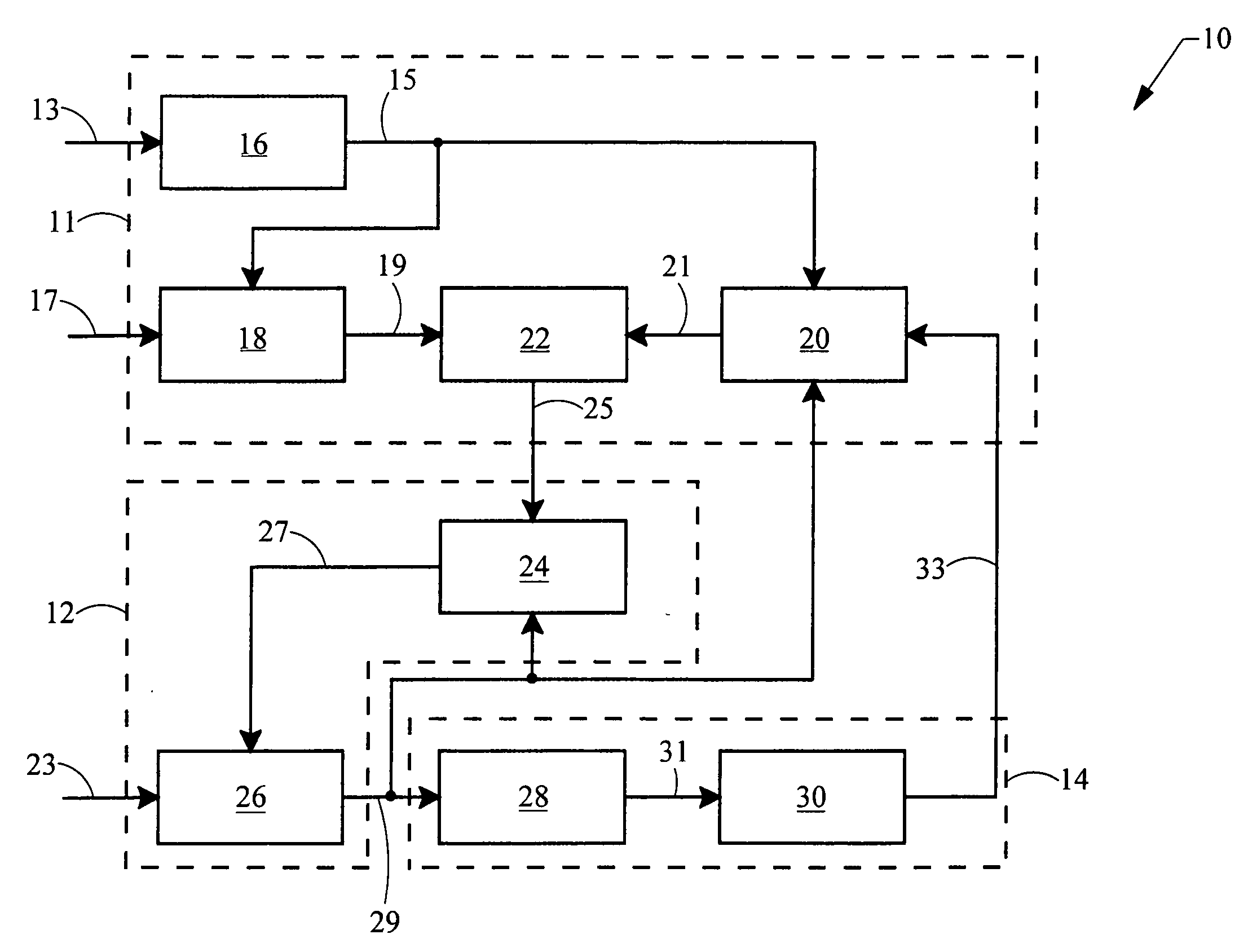
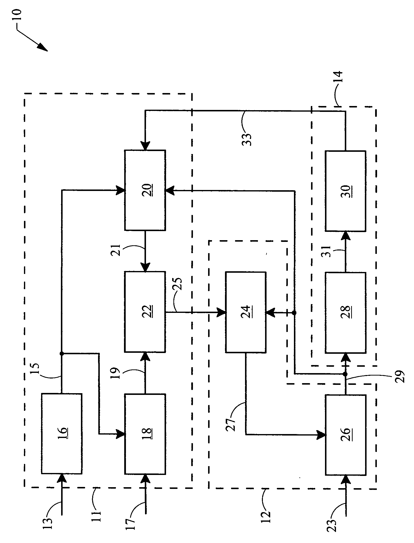
[0013] Referring now to the FIGURE, the components of a variable distortion limiter using clip detect predictor are shown. The variable distortion limiter using clip detect predictor system 10 includes a microprocessor 11, a digital signal processor (“DSP”) 12 and an amplifier 14.

[0014] The microprocessor 11 includes a filter 16 for filtering the supply voltage 13 of the amplifier 14. By way of example, the filter 16 uses a ten bit analog-to-digital converter that will convert the supply voltage 13 to a digital value, and filters the digital value in software. However, the filter 16 may be any device for filtering the supply voltage. For example, the filter 16 could be an analog low pass filtering device. In operation, the filter 16 will sample a plurality of values representing the supply voltage and average the plurality of values to obtain and output a reference supply voltage value 15 (“VRef”) as measured in volts.

[0015] Further disposed within the microprocessor 11 is a varia...


PUM


Abstract

A system and method for predicting and limiting distortion of an amplified signal is described. The system includes a variable total harmonic distortion (“THD”) clipping predictor, a comparator in communication with the variable THD clipping predictor and a distortion limiter in communication with the comparator. As for the method, a reference power supply value, a maximum desired total harmonic distortion value and a preamplified signal value is provided. A THD output threshold value is calculated based on the reference power supply value and the maximum desired THD value and is then compared to the preamplified signal value. Depending on if the preamplified signal value is greater than or less than the THD output threshold value, the amplitude of the preamplified signal may be increased or decreased.

Description

BACKGROUND [0001] 1. Field of the Invention [0002] The present invention generally relates to audio signal clipping and distortion limiting systems. [0003] 2. Description of the Known Technology [0004] Automotive audio systems have an amplifier which amplifies a preamplified audio signal. However, the magnitude of the amplification of the preamplified audio signal is limited by the source voltage that powers the amplifier. If the amplifier is provided with a preamplified audio signal of an amplitude such that the magnitude of the amplified signal will exceed the voltage powering the amplifier, a clipped amplified signal will be generated by the amplifier. When clipping occurs, THD can be increased to an undesirable level. [0005] Current solutions to this problem involve monitoring the output of the amplifier to determine if a clipped signal is generated. Once a clipped signal is detected, the preamplified signal is adjusted to limit the amount of THD induced by clipping. Current sol...

Claims


Application Information

Patent Timeline
Patent Type & Authority Applications(United States)
IPC IPC(8): H03F1/26
CPCH03G3/301H03F1/3264
Inventor KROCHMAL, ANDREW C.WHITECAR, JOHN E.STEWART, DAVID P.
Owner VISTEON GLOBAL TECH INC
Why Eureka
Try Eureka