Rotary actuator and input device using the same

a technology of input device and rotary actuator, which is applied in the direction of mechanical control device, gearing, pulse technique, etc., can solve problems such as rotation noise, and achieve the effect of simple structure and preferable operation feeling

Active Publication Date: 2012-03-06
PANASONIC CORP
View PDF20 Cites 9 Cited by
  • Summary
  • Abstract
  • Description
  • Claims
  • Application Information

AI Technical Summary

Benefits of technology

[0012]This rotary actuator has a simple structure and operates with a preferable operation feeling.

Problems solved by technology

This may cause a rotation noise due to a shock when roller 1 is operated.

Method used


Image

  • Rotary actuator and input device using the same
  • Rotary actuator and input device using the same
  • Rotary actuator and input device using the same

Examples


Embodiment Construction

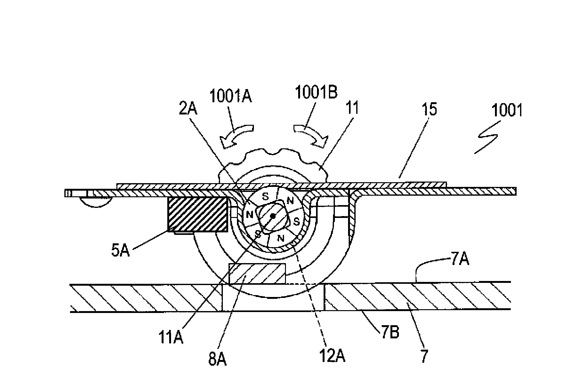
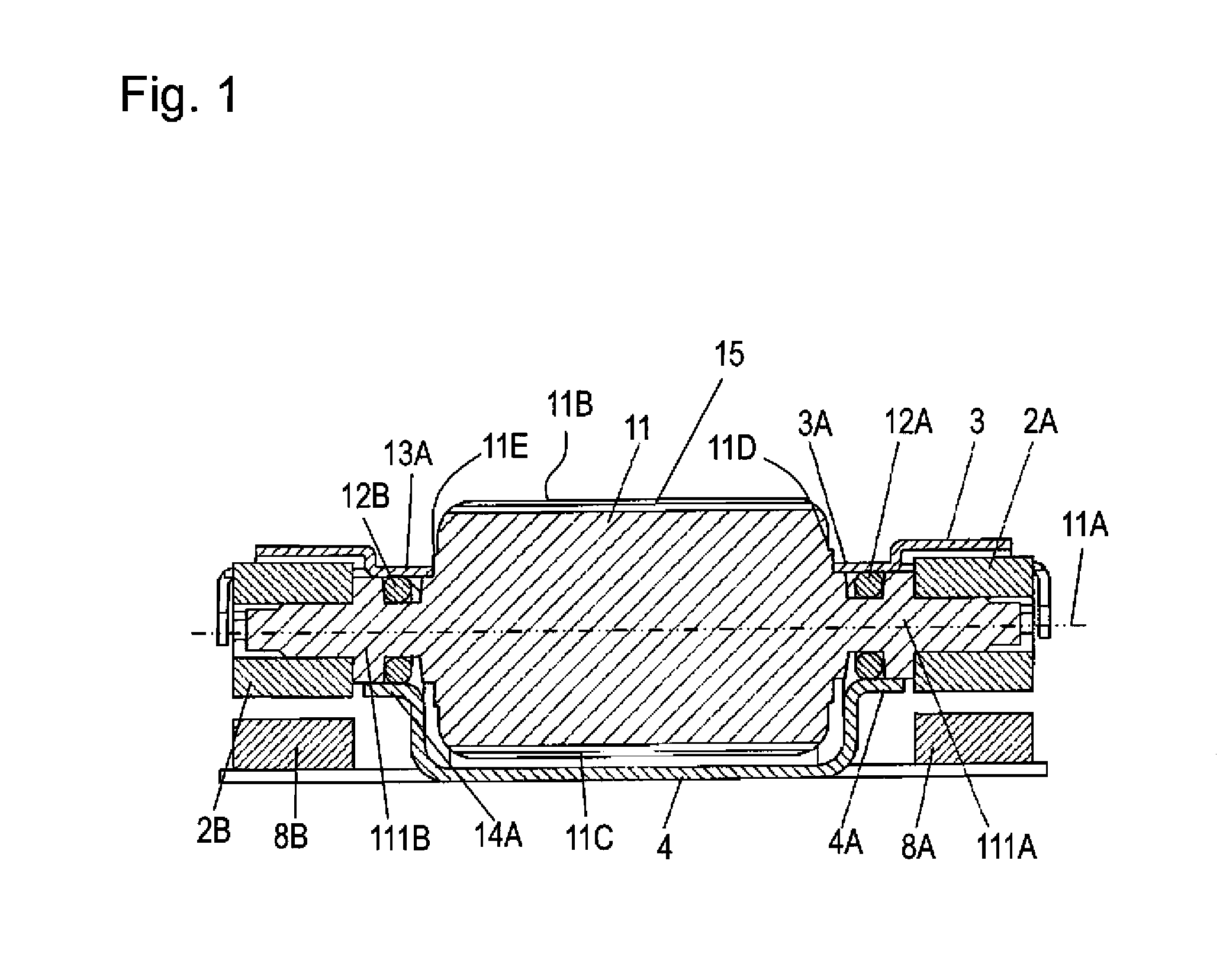
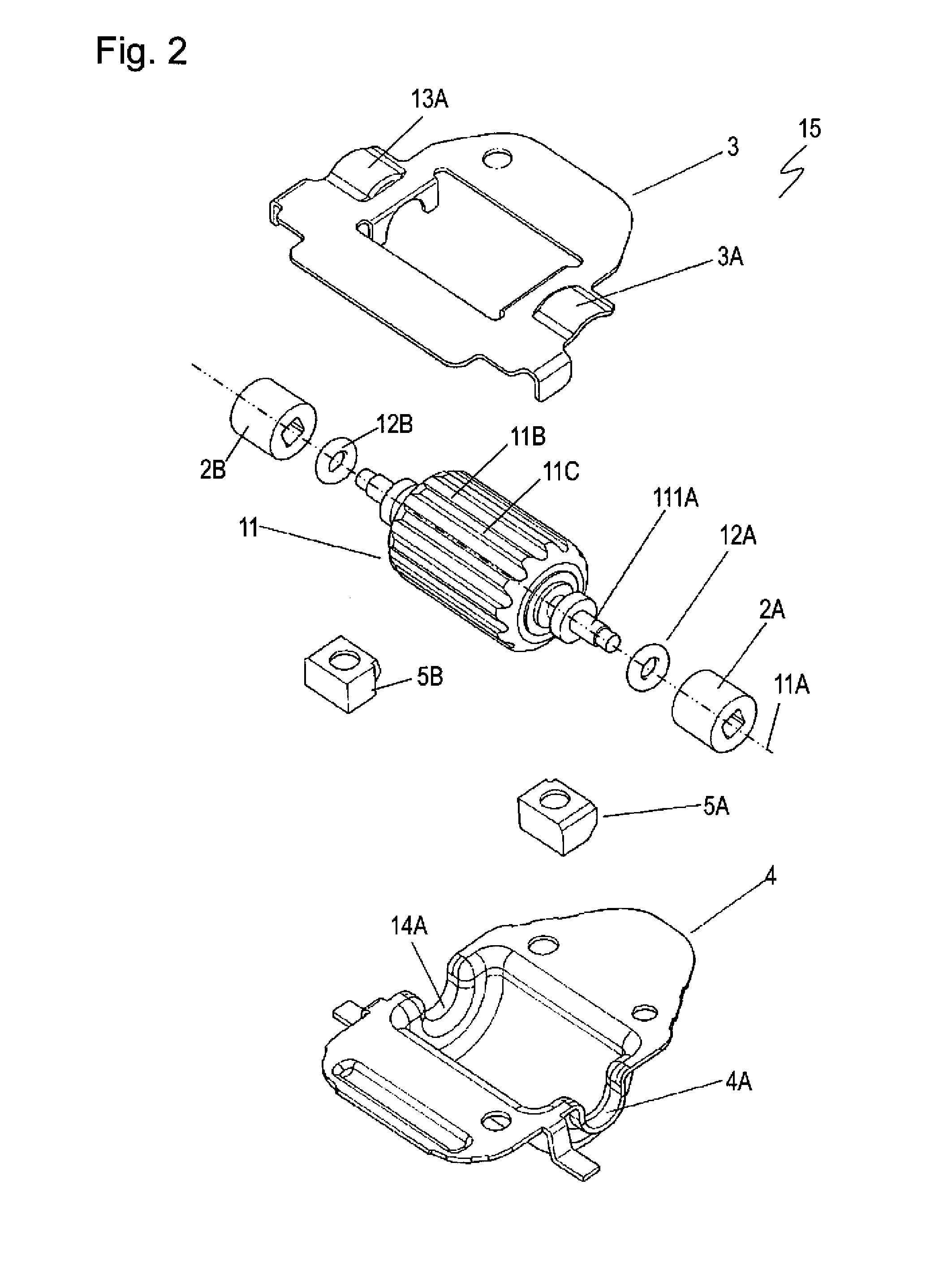
[0019]FIGS. 1 and 2 are a front sectional view and an exploded perspective view of rotary actuator 15 according to an exemplary embodiment of the present invention, respectively. Roller 11 is made of metal, such as aluminum, or insulating resin and has substantially a columnar shape having center axis 11A. Grooves 11C extending in parallel to center axis 11A are provided in outer circumferential surface 11B of roller 11. Center shafts 111A and 111B protrude from end surfaces 11D and 11E along center axis 11A of roller 11, respectively.

[0020]Ring magnet 2A is alternately magnetized to S-poles and N-poles with predetermined angular intervals. Ring magnet 2B is alternately magnetized to S-poles and N-poles with angular intervals identical to those of ring magnet 2A. Ring magnets 2A and 2B are fixed to center shafts 111A and 111B, respectively, while the positions of the S-poles and the N-poles are deviated by a predetermined angular phase difference.

[0021]Upper cover 3 and lower cover ...


PUM


Abstract

A rotary actuator includes a roller having a center shaft protruding along a center axis, a bearing for supporting the center shaft of the roller to allow the roller to rotate about the center axis, a ring magnet fixed to the center shaft of the roller, an elastic member having a ring shape provided between the center shaft of the roller and the bearing, and a fixed magnet facing the ring magnet. The ring magnet is alternately magnetized to an S-pole and an N-pole with predetermined angular intervals. This rotary actuator has a simple structure and operates with a preferable operation feeling.

Description

FIELD OF THE INVENTION[0001]The present invention relates to a rotary actuator to be used for operating various electronic devices, and to an input device using the rotary actuator.BACKGROUND OF THE INVENTION[0002]As various electronic apparatuses, such as mobile phones and video cameras, have recently had small sizes and high functions, rotary actuators and input devices have been demanded to perform various operations of the apparatuses with a preferable feeling during operation.[0003]FIGS. 4 and 5 are a front sectional view and an exploded perspective view of a conventional rotary actuator 6, respectively. Roller 1 has a substantially columnar shape and is made of metal or insulating resin. An outer circumferential surface of roller 1 has recesses. Roller 1 has center shafts 1A protruding from both ends of roller 1. Ring magnet 2 is alternately magnetized to S-poles and N-poles with predetermined angular pitches. Ring magnet 2 is fixed to each end of center shafts 1A of roller 1....

Claims


Application Information

Patent Timeline
Patent Type & Authority Patents(United States)
IPC IPC(8): H03K17/94H03M11/00
CPCG01D5/145G01D11/14G05G5/03G05G1/10Y10T74/1836H03K2217/94068
Inventor INOUE, HIROTOYAMAMOTO, TAMOTSU
Owner PANASONIC CORP
Why Eureka
Try Eureka