
Biological unit removal tools with concentric tubes

a technology of biological units and tools, applied in the field of tools, can solve the problems of less desirable follicular units, and achieve the effect of effectively penetrated tissue and increasing the yield of usable harvested

Active Publication Date: 2012-03-13
VENUS CONCEPT INC
View PDF107 Cites 33 Cited by
  • Summary
  • Abstract
  • Description
  • Claims
  • Application Information

AI Technical Summary

Benefits of technology

The method improves the yield and quality of harvested follicular units by minimizing damage and retention issues, allowing for more effective and efficient hair transplantation procedures.

Problems solved by technology

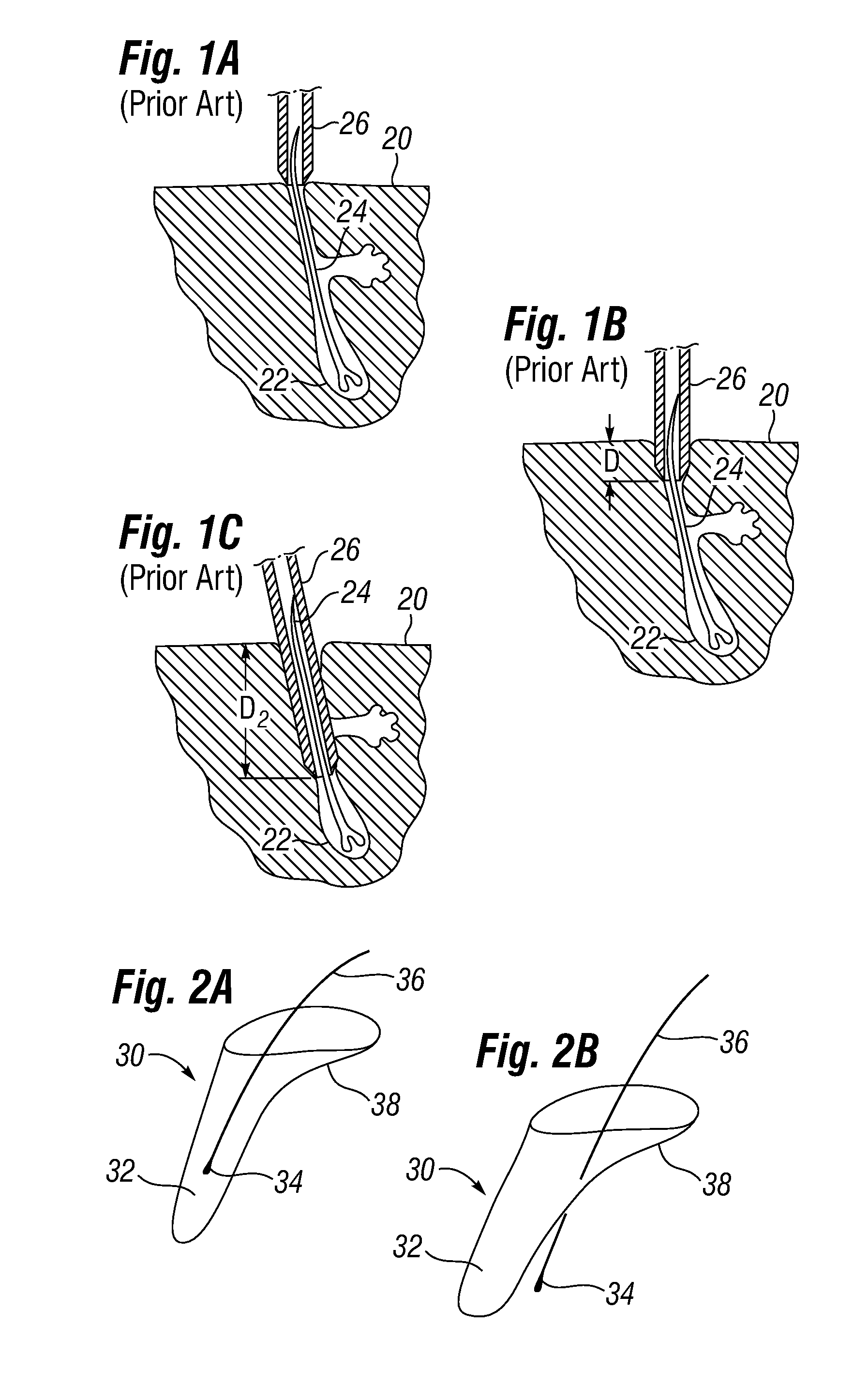
Sometimes, the sharp end of the needle punch cuts through, or transects, the hair shaft, rendering the follicular unit less than desirable.
At other times, the incident angle at which the hollow punch contacts the skin surface causes the punch to stretch the skin and cut a relatively large flap of surrounding tissue along with the hair follicle, which may interfere with a subsequent implant procedure.
However, because the cannula advances into the skin at an angle, an undesirable lateral flap 38 of skin in the direction that the cannula is angled may result.
Moreover, in case of subsequent implantation of the harvested hair, the existence of the flap 38 interferes with the preference for small and closely spaced incisions at the implantation site. FIG. 2B shows an additional problem associated with the sliding of the cannula before a complete penetration of the skin while being advanced at an angle which results again in the creation of the flap and also in biological unit 30 being transected along the shaft 36.
These two problems are typical reasons for discarding harvested biological units 30 used in hair transplantation, and may also be undesirable for biopsy or other applications where specimens of biological tissue need to be taken.

Method used


Image

  • Biological unit removal tools with concentric tubes
  • Biological unit removal tools with concentric tubes
  • Biological unit removal tools with concentric tubes

Examples


Embodiment Construction

[0088]In the following Detailed Description, reference is made to the accompanying drawings that show by way of illustration some exemplary embodiments in which the invention may be practiced. In this regard, directional terminology, such as “top,”“bottom,”“front,”“back,”“distal,”“proximal,” etc., is used with reference to the orientation of the Figure(s) being described. Because components or embodiments of the present invention can be positioned in a number of different orientations, the directional terminology is used for purposes of illustration and is in no way limiting. It is to be understood that other embodiments may be utilized and structural or logical changes may be made without departing from the scope of the present invention. The following description, therefore, is not to be taken in a limiting sense, and the scope of the present invention is defined by the appended claims.

[0089]The adjective “automated” with reference to a system or process as a whole means that some...


PUM


Abstract

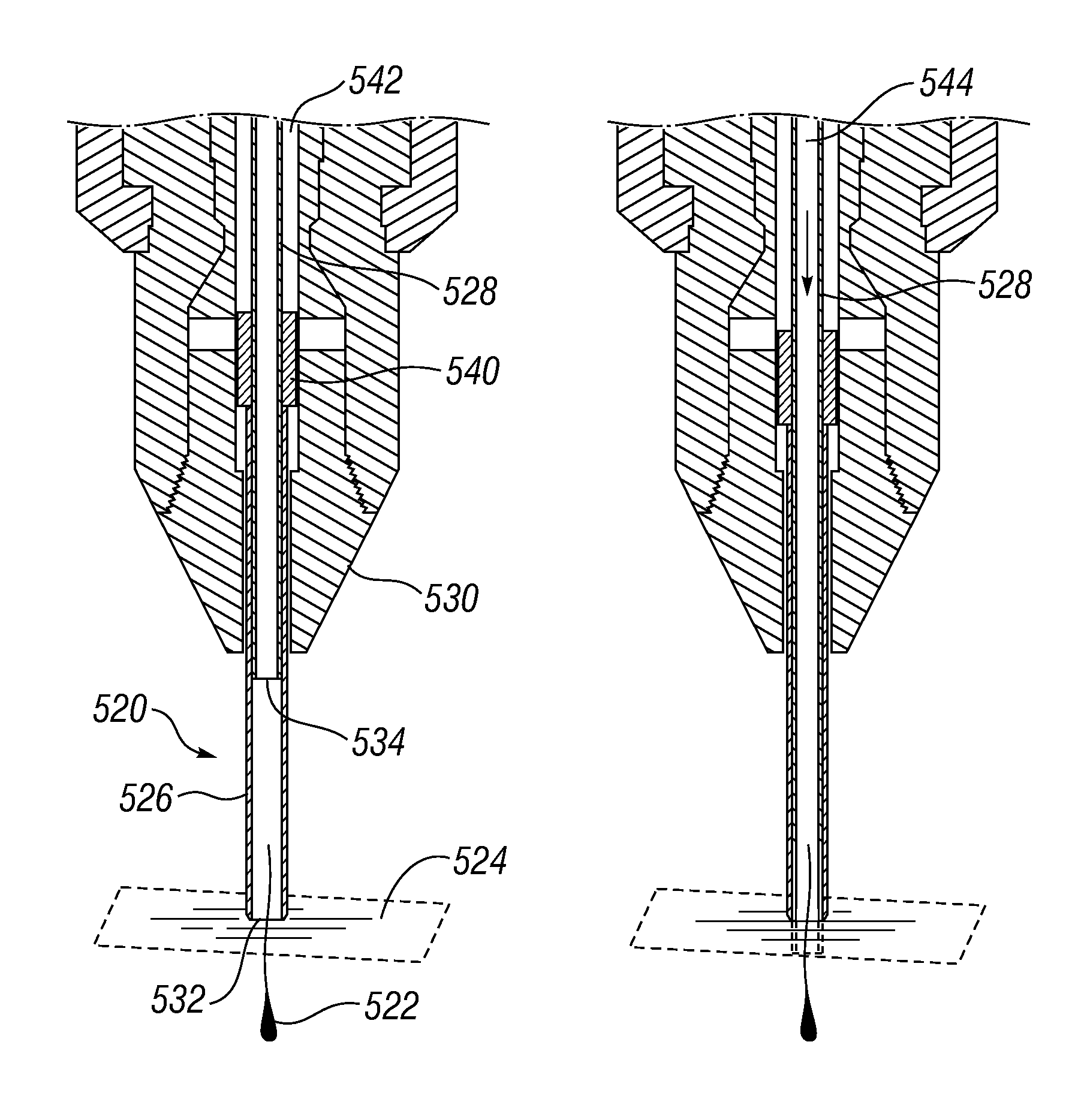
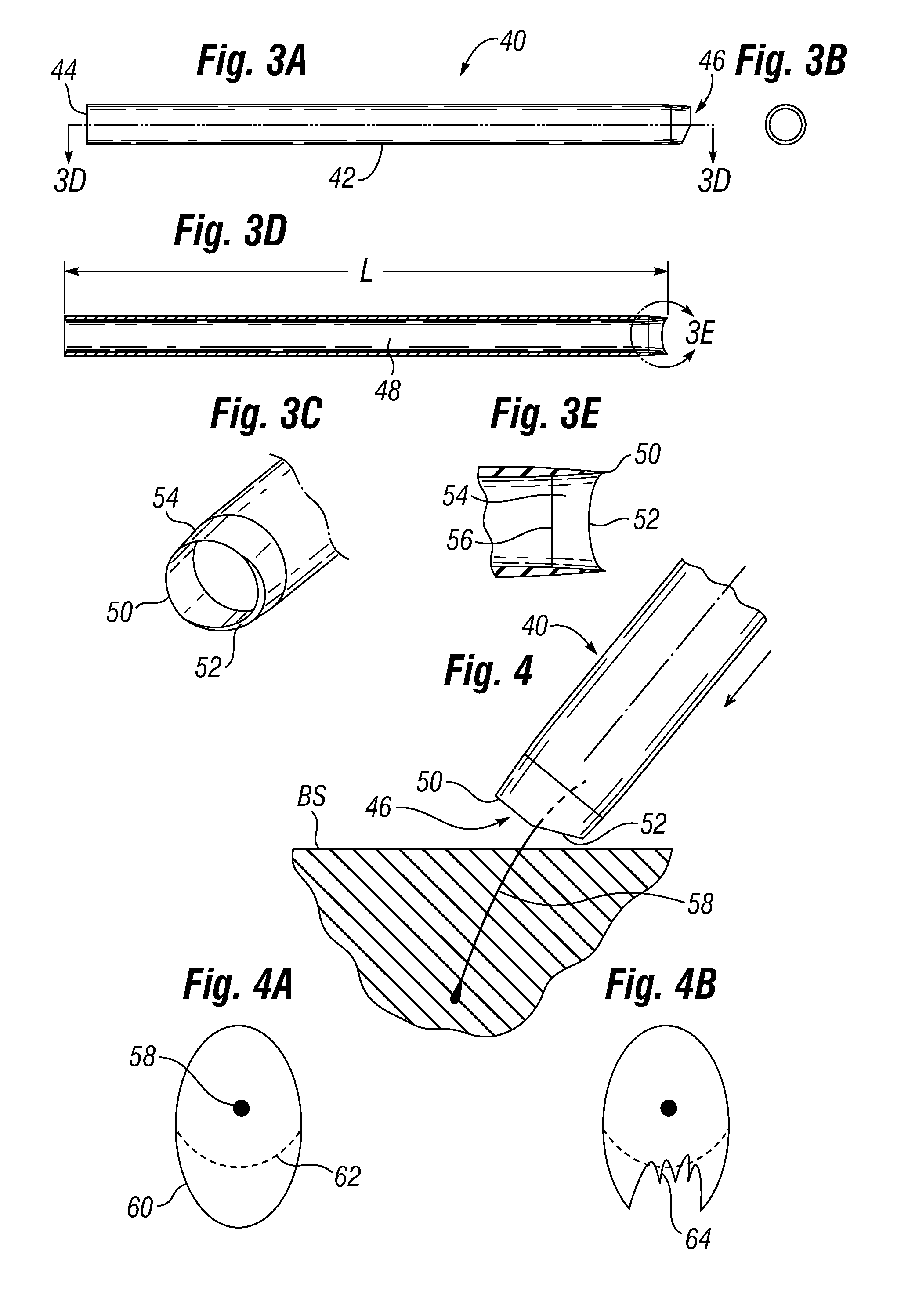
Tools and methods are provided for removing biological units from a body surface utilizing a removal tool. The tools may incorporate retention members and mechanisms configured to impede movement of the biological unit in the direction of a distal end of the tool and to improve retention of the biological unit in the tool. Some of the retention members are stationary and some are movable within the lumen of the biological unit removal tools. The distal tips of the tools are desirably configured to reduce the chance of transection of a biological unit, such as by including both cutting segments and blunt relief segments. A number of dual concentric tube embodiments permit a division of removal functions. Distal fluid or gas delivery may supplement a vacuum in a luminal space to help extract biological units from surrounding tissue.

Description

RELATED APPLICATIONS[0001]This application claims priority under 35 U.S.C. §119(e) to U.S. Provisional Application No. 60 / 895,530, filed Mar. 19, 2007, and entitled DEVICES AND APPARATUS FOR HARVESTING FOLLICULAR UNITS.FIELD OF THE INVENTION[0002]This invention relates generally to tools used for the harvesting of various biological tissue samples, including hair follicles.BACKGROUND OF THE INVENTION[0003]There are various known tools and instruments for removing biological tissue samples from the body. For example, biopsy needles and punches are used when a small tissue specimen is required for examination, for example, to identify certain medical conditions. Another example of the biological tissue which is often desired to be removed or harvested is a hair follicle. Hair transplantation procedures are well-known, and typically involve harvesting donor hair grafts from the “donor areas,” for example, side and back fringe areas of the patient's scalp, and implanting them in a bald ...

Claims


Application Information

Patent Timeline
Patent Type & Authority Patents(United States)
IPC IPC(8): A61B17/50
CPCA61B10/0266A61B17/32053A61B17/322A61F2/10A45D26/00A61B10/0275A61B17/32093A61B2010/0208A61B2017/00969A61B2017/320064A61B2217/005A61B2217/007A61B2017/00752A61B10/02A61B17/32A61B17/3203
Inventor OOSTMAN, JR., CLIFFORD A.CANALES, MIGUEL G.
Owner VENUS CONCEPT INC
Learn More