Dual stage positioning and switching system

a switching system and dual stage technology, applied in the field of motion positioning techniques, can solve the problems of increasing the cost of the dual stage structure, the difficulty of positioning and switching the two stages, and the overlap of the stages paths, so as to improve the reliability of the system, simplify the structure of the system, and eliminate interferen

Active Publication Date: 2012-03-13
SHANGHAI MICRO ELECTRONICS EQUIP (GRP) CO LTD
View PDF9 Cites 2 Cited by
  • Summary
  • Abstract
  • Description
  • Claims
  • Application Information

AI Technical Summary

Benefits of technology

[0007]It is an object of the present invention to provide a dual stage positioning and switching system, which does not need to include a cable stage moving synchronously with the wafer stage, so that the structure is simplified.
[0012]Compared with the known art, the present invention has the advantage that the two workstations of the dual stage structure do not overlap, eliminating the interference between the two stages, and thereby improving the reliability of the system.
[0013]Besides, there is no cable stage included in the present system, so that the structure of the system is simplified, and the influence on the positioning accuracy of the system caused by distorted cables is effectively reduced.

Problems solved by technology

Present dual stage structures can achieve the positioning and switching of two wafer stages, but there remain some disadvantages of the present structures: since a wafer stage has a lot of cables connected thereto, such as the gas supplying pipelines, the control lines for adjusting the vertical (Z-direction) positions of the wafer stages, cables of the sensors for detecting the X and Y direction positions of the wafer stages and other sensor circuits, cables of the circuit that controls the loading and unloading of the wafer, etc.
The operation of the cable stage directly influences the motion positioning accuracy and the dynamic performance of the wafer stage, thus increasing the cost of the dual stage structure as well as the difficulty in the positioning and switching of the two stages.
Moreover, during the synchronous operations of the two stages, due to the overlapped work space, the stages are likely to interfere with each other, and the paths of the stages may also overlap.
Therefore, devices for preventing collision between the stages are needed, so that the manufacturing cost is raised.

Method used


Image

  • Dual stage positioning and switching system
  • Dual stage positioning and switching system
  • Dual stage positioning and switching system

Examples


Embodiment Construction

[0025]The present invention will be described in detail by reference to the drawings and the preferred embodiment. The preferred embodiment is a dual stage positioning and switching system used in the field of lithography machine manufacturing.

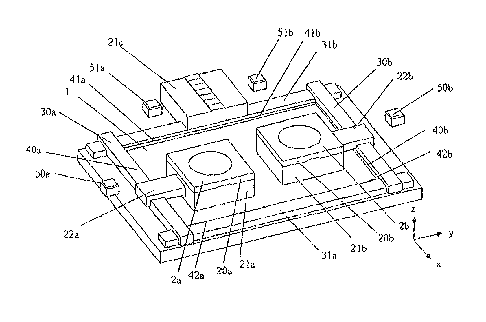
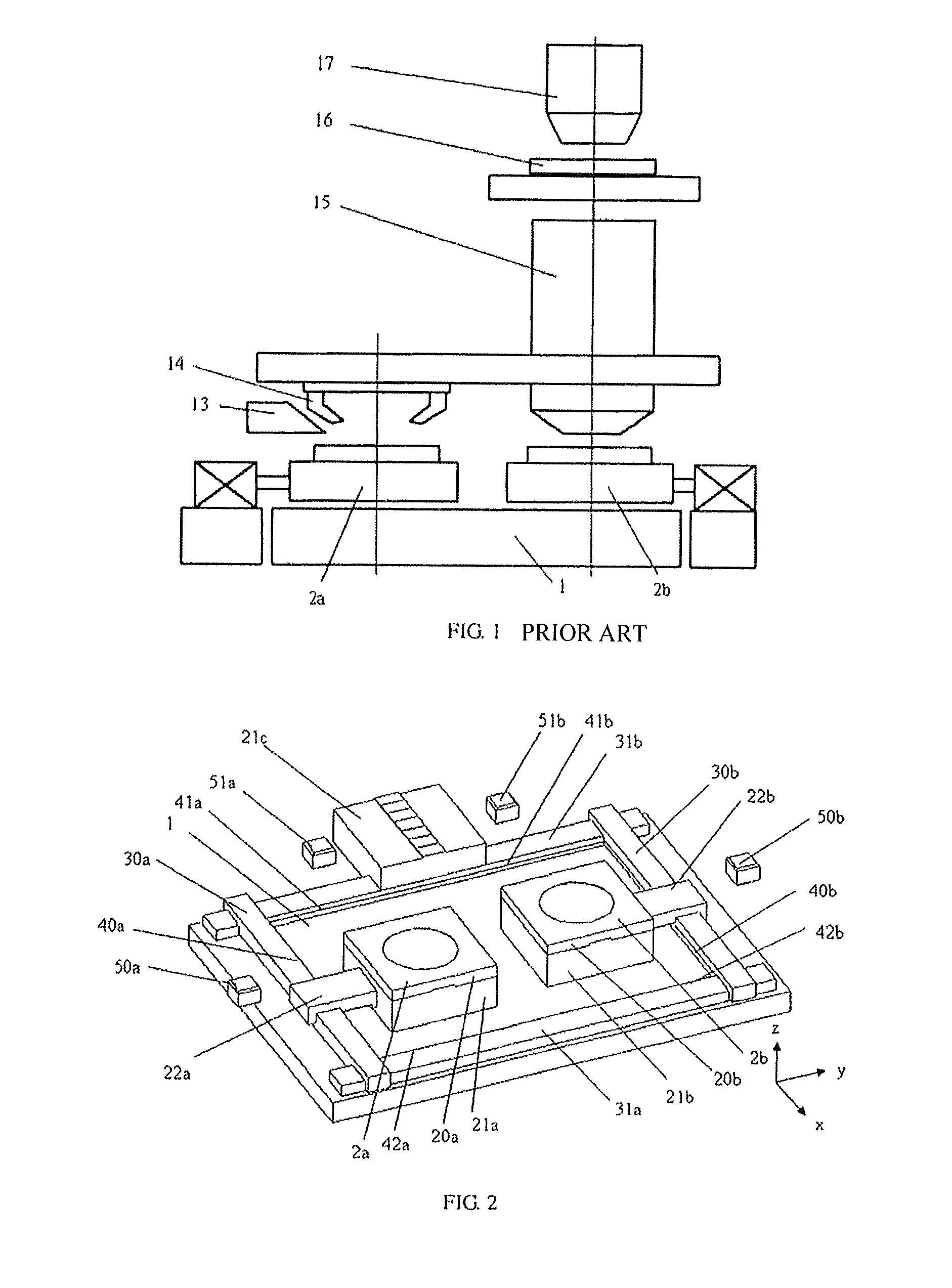
[0026]FIG. 2 shows a layout of the dual stage positioning system of the present invention. The system comprises a base 1, a first wafer stage positioning unit disposed on the base 1 for a pre-processing workstation, and a second wafer stage positioning unit disposed on the base 1 for an exposure workstation. The first wafer stage positioning unit for the pre-processing workstation comprises a wafer supporting structure 2a, a driver 22a, motion positioning detectors 50a, 51a, an X-direction guide bar 30a, Y-direction guide bars 31a, 31b, and linear gratings 40a, 41a, 42a disposed respectively on the guide bars. The second wafer stage positioning unit for the exposure workstation comprises a wafer supporting structure 2b, a driver 22b, motion po...


PUM


Abstract

The present invention has disclosed a dual stage positioning and switching system, which comprises at least a base, a first object stage positioning unit disposed on the base for a first workstation, and a second object stage positioning unit for a second workstation. Each of the object stage positioning units comprises at least a supporting structure, an X-direction guide bar, a Y-direction guide bar, and a motion positioning detector, wherein, the supporting structure comprises an object stage, and an object stage connector moving relative to the object stage. The object stage positioning unit further comprises a driver connecting to the object stage connector and driving the connector to move along the X-direction guide bar. The X-direction guide bars are positioned on and movable along the Y-direction guide bars. The system further comprises an object stage connector for transitional use during the switching process, which is positioned at the center of the Y-direction guide bar located on one side of the base. The present system does not include a cable stage, so that the structure of the system is simplified.

Description

TECHNICAL FIELD[0001]The present invention relates to the field of motion positioning techniques, particularly to a dual stage positioning and switching system.BACKGROUND ART[0002]A dual stage positioning and switching system is used for the switch of two wafer stages. The wafer stages cooperate with the base, X-direction guide bars, Y-direction guide bars, motion positioning detectors, linear gratings, etc. to complete the switching process. The above system can be used in the field of lithography machine manufacturing.[0003]A lithography machine, which exposes and transfers the design pattern of a chip onto the photoresist coated on a wafer, is one of the important devices used in IC chip manufacturing. A main part of a lithography machine is the wafer stage positioning and switching system, whose operation accuracy and running speed greatly influences the throughput of a lithography machine.[0004]A complete exposure process comprises such sub-processes as wafer loading, pre-align...

Claims


Application Information

Patent Timeline
Patent Type & Authority Patents(United States)
IPC IPC(8): G03B27/58G03B27/60
CPCG03F7/70716G03F7/70733G03F7/70758
Inventor LI, XIAOPINGLI, YINGSHENG
Owner SHANGHAI MICRO ELECTRONICS EQUIP (GRP) CO LTD
Why Eureka
Try Eureka