Evaporator for a cooling circuit

a cooling circuit and evaporator technology, applied in the field of evaporators for cooling circuits, can solve the problems of difficult leak proof at high pressure, poor heat transfer performance of pool-boiling, and relatively low efficiency of evaporators

Inactive Publication Date: 2012-03-13
ABB RES LTD
View PDF28 Cites 2 Cited by
  • Summary
  • Abstract
  • Description
  • Claims
  • Application Information

AI Technical Summary

Benefits of technology

[0019]As it was explained when discussing known convection boiling, the temperature of the liquid flowing through the small gap reaches the boiling temperature. Consequently the gas flow transports also a certain amount of the liquid phase. According to the present disclosure the evaporator also includes at least one separation volume. The at least one separation volume, hereinafter also referred to simply as the separation module for enhanced readability, is located at a vapor exiting port of the channel. Thus, when the cooling circuit is in use, the vapor / liquid mixture is introduced from the at least one channel into the separation volume. So before the flow of vapor exits the evaporator, the phase separation occurs and the liquid phase fraction is not conveyed to the condenser. It is rather dropped back into a liquid reservoir which is furthermore arranged in the evaporator.
[0020]An exemplary advantage of the evaporator according to the present disclosure is that a circuit for cooling a heat emitting device using the evaporator can take advantage of both effects. On one hand, heat transfer between the heat emitting device and the liquid inside the evaporator can be improved by providing one or a plurality of parallel channels as a confined space in which a convection boiling takes place. On another hand, an adverse effect of the convection boiling in such a confined gap to the performance of the condenser can be avoided as the condenser of such a cooling circuit is fed with the vapor phase only. The separation of the liquid phase and the vapor phase is conducted inside the separation volume which is arranged subsequent to the channel in the direction of flow. Furthermore as the evaporator also includes a liquid reservoir, it is not necessary to provide a pump or the like in order to supply a sufficient amount of liquid at all the time.
[0024]Such an enlarged gap at the vapor exiting port of the channel can have the advantage that the overall dimensions of the evaporator can be kept low. Such a gap automatically leads to an enlarged distance between the vapor exiting port of the channel and an entrance of a vapor conduit connecting the evaporator with a condenser. This area between the vapor exiting port and the entrance of the vapor conduit constitutes the separation volume that can be built easily by the length shorter than the inside surface of the wall of the evaporator.
[0025]For easy manufacturing, it can be an advantage to provide the channel building element as an insert. Such an insert can furthermore have an advantage that the shape of known evaporators may be maintained without the need of developing a new design. Furthermore such an insert to be inserted in an evaporator housing allows a large variety of channel or gap dimensions as well as sizes of the liquid reservoir. Consequently it is easy to adjust the size of the liquid reservoir for providing optimal performance according to the global shape of the evaporator.
[0026]Further it can be advantageous to provide at least one spacing means between the inside surface of the wall of the evaporator housing and the at least one surface of the inserted channel building element. In other words, the inside surface can be displaced about a first distance from a first surface of the at least one heat emitting device by means of at least one spacing means. Providing such a spacing means can allow, in a very easy and comfortable way, positioning of the insert correctly inside of the evaporator housing. Depending on the desired requirements and on the manufacturability, the spacing means comprises at least one spacer element that is at least partially integrated in an least one of the wall and the first surface. In addition or alternatively thereto, the spacing means can be formed by at least one separate element.
[0027]It can be furthermore advantageous to constitute the liquid reservoir by forming a recess in the channel building element. As such evaporators or thermosyphons have a well-defined orientation during use because of the vapor phase bubbles going up in the liquid phase, it can be assumed that the inside surface of the wall of the housing of the evaporator and the first side of the channel building element are arranged in an at least approximately vertical direction. Consequently the channel extends in a vertical direction with the liquid introduction port formed at the bottom of the evaporator and the vapor exiting port being positioned at the upper end of the channel. The recess can be therefore advantageously a recessed portion arranged at the top side of the channel building element.

Problems solved by technology

Consequently the efficiency of the evaporator can be relatively low.
This so-called “pool-boiling” can have poor heat transfer performance, can be bulky, can involve a large fluid inventory, and can be difficult to make leak proof at high pressure.
As such, a positive effect of reduction of the cross section area of the evaporator can be undermined to a large extent by the poor heat transfer performance of the condenser.

Method used


Image

  • Evaporator for a cooling circuit
  • Evaporator for a cooling circuit
  • Evaporator for a cooling circuit

Examples


Embodiment Construction

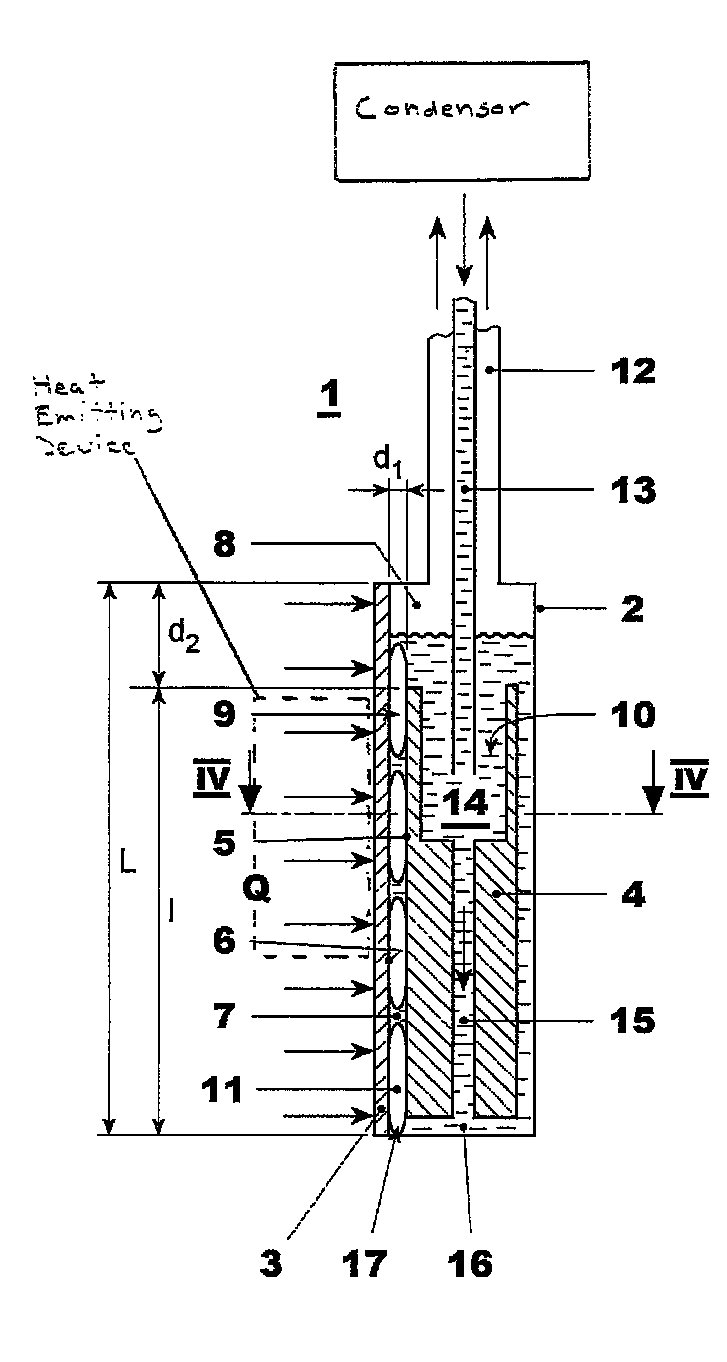
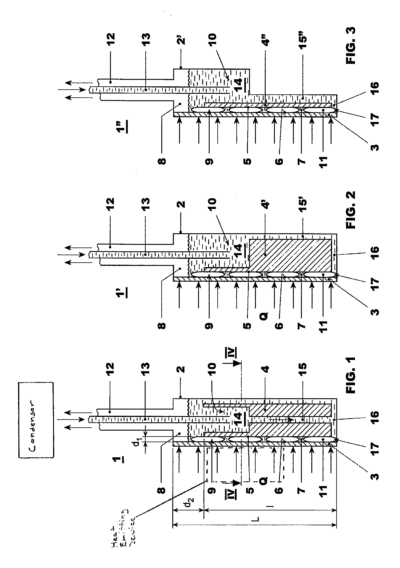
[0015]In exemplary embodiments, an evaporator for a cooling circuit of a power module is disclosed which can, for example, provide an improved heat transfer without affecting the performance of a condenser of the cooling circuit.

[0016]The term power module is understood hereinafter as, for example, an assembly having at least one power electronic and / or power electric device, that is thermally connected to at least one cooling circuit. Moreover, the terms power electronic and / or power electric device and heat emitting device are used in an interchangeable manner hereinafter.

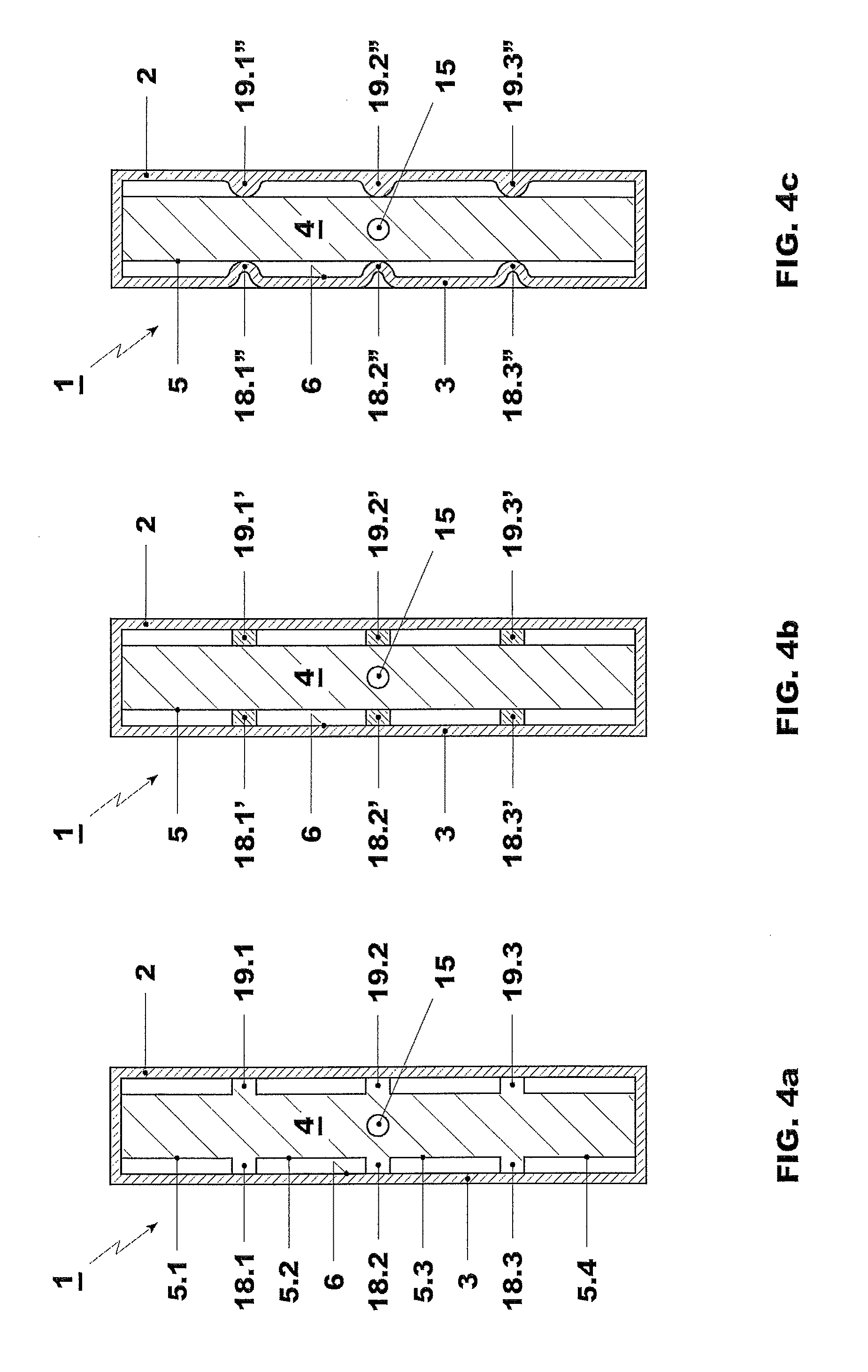
[0017]As to the cooling circuit, exemplary embodiments include the following characteristics: a cooling circuit for cooling at least one heat emitting device, wherein the cooling circuit includes an evaporator. The evaporator in turn includes a housing having at least one wall that is thermally connectable with (i.e., configured for connection with) the at least one heat emitting device. The evaporator further in...


PUM


Abstract

An evaporator is disclosed for a cooling circuit. The evaporator includes a housing having at least one wall for contacting a heat emitting device. A channel, the cross section of which is small enough to allow convection boiling, and a separation volume are located in the evaporator. The separation volume is located at a vapor exiting port of the channel. The evaporator can include a liquid reservoir.

Description

RELATED APPLICATION[0001]This application claims priority under 35 U.S.C. §119 to European Patent Application No. 08156175.5 filed in Europe on May 14, 2008, the entire content of which is hereby incorporated by reference in its entirety.TECHNICAL FIELD[0002]A cooling circuit is disclosed, such as a two-phase cooling circuit, for cooling at least one of a power electronic and a power electric device, and / or a power module comprising such a cooling circuit.BACKGROUND INFORMATION[0003]As power electronic devices reach larger and larger power values and consequently emit more heat, efficient cooling of such power electronic devices becomes more and more important. One way of providing an efficient cooling system for such power electronic devices, for example semi-conductor switching elements or the like, is to provide a two-phase cooling circuit. Such a cooling circuit brings a liquid into thermal contact with the device emitting heat. The liquid is heated by the emitted heat and reach...

Claims


Application Information

Patent Timeline
Patent Type & Authority Patents(United States)
IPC IPC(8): H05K7/20
CPCF28D15/0266
Inventor AGOSTINI, BRUNOYESIN, BERK
Owner ABB RES LTD
Why Eureka
Try Eureka