
Locking device

a technology of locking device and locking plate, which is applied in the direction of sliding fasteners, metal working apparatus, apparel, etc., can solve the problems of design freedom decline and inefficient assembly work of shavers, and achieve the effect of enhancing assembly work efficiency

Inactive Publication Date: 2012-03-20
IZUMI PROD CO
View PDF18 Cites 8 Cited by
  • Summary
  • Abstract
  • Description
  • Claims
  • Application Information

AI Technical Summary

Benefits of technology

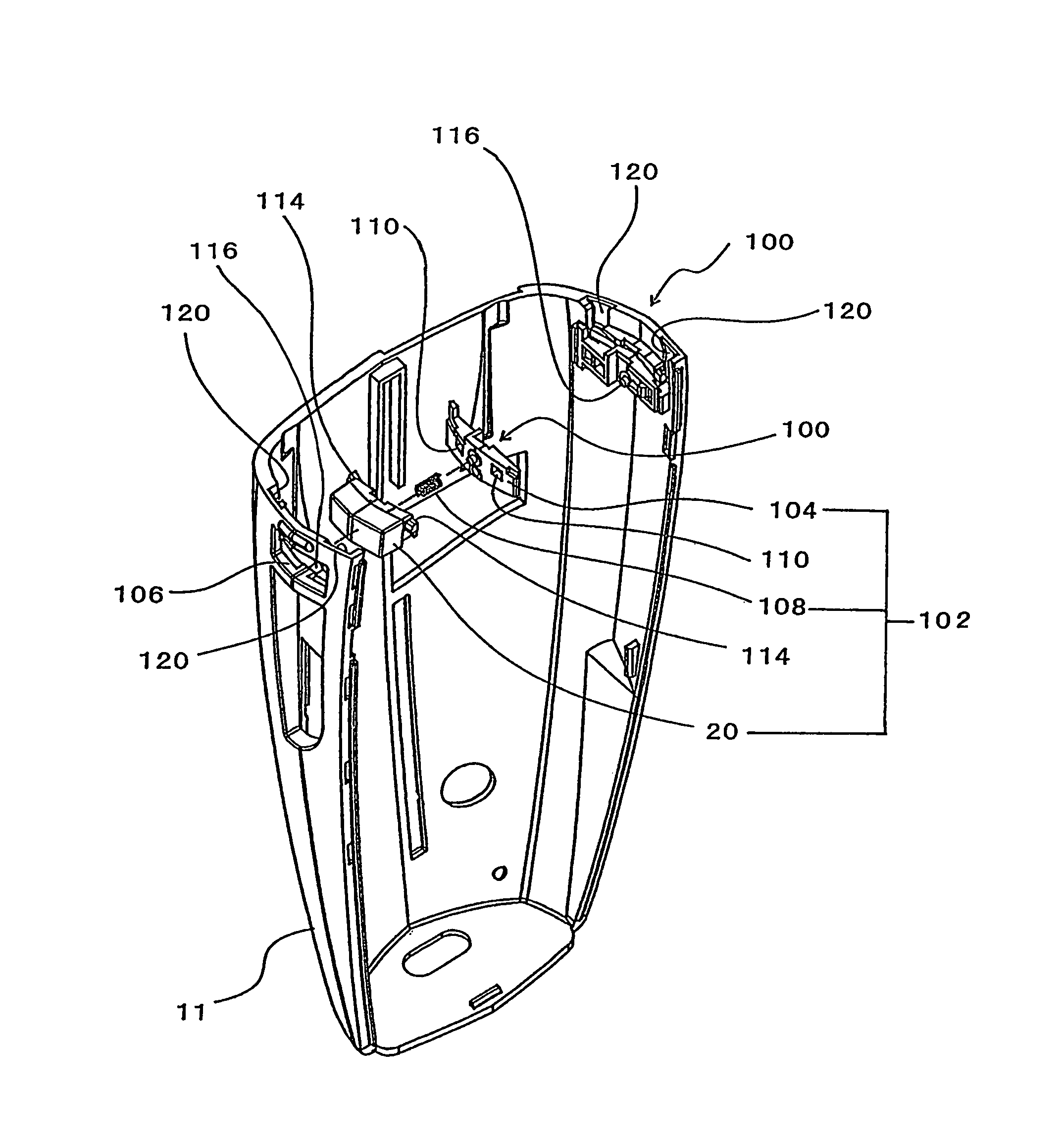
[0009]Accordingly, an object of the present invention, devised in view of the above-described circumstances, is to provide a locking device in which the locking device can be assembled irrespective of assembly of a main body of, for instance, an electric shaver, thus enhancing assembly work efficiency, and in which a push button return spring load is prevented from acting on the main body casing or on the parts installed inside the main body, making it unnecessary to provide reinforcing ribs or the like in the shaver main body casing or in the parts mounted inside the main body, and further in which molding die design freedom can be increased.
[0017]In the locking device of the present invention, a push button assembly is formed by compressing and mounting a push button return spring between a push button and a back panel, and the push button and the back panel are engaged with each other so as to limit the amount by which the push button protrudes, and the thus structured push button assembly is mounted by securing the back panel thereof to the inner surface of either the main body or the attachment member. Accordingly, the locking device can be assembled irrespective of the assembly of the parts installed in the main body, and assembly work efficiency is enhanced. In addition, because the push button return spring load is received by the back panel and push button, there is no longer any necessity of providing reinforcing ribs or hubs for taking such loads in the main body casing or in the parts in the main body or the like, and molding die design freedom increases.
[0024]In the above structure, guide channels can bee formed in the inner surface of the main body casing for guiding the first engagement pawls into the gap between the main body casing inner surface and the second engagement pawls. With such guide channels, the engagement and disengagement of the first engagement pawls and the second engagement pawls can be performed smoothly.

Problems solved by technology

Accordingly, the installation of such parts in the main body and the installation of the locking device must be performed in parallel, making the assembly work of shavers inefficient.
This has been a problem.
When those parts are molded products made of resins (plastics), limitations arise on the shapes of the parts in terms of the structure of the molding dies, and thus design freedom declines, which is also a problem.

Method used


Image

  • Locking device
  • Locking device
  • Locking device

Examples


Embodiment Construction

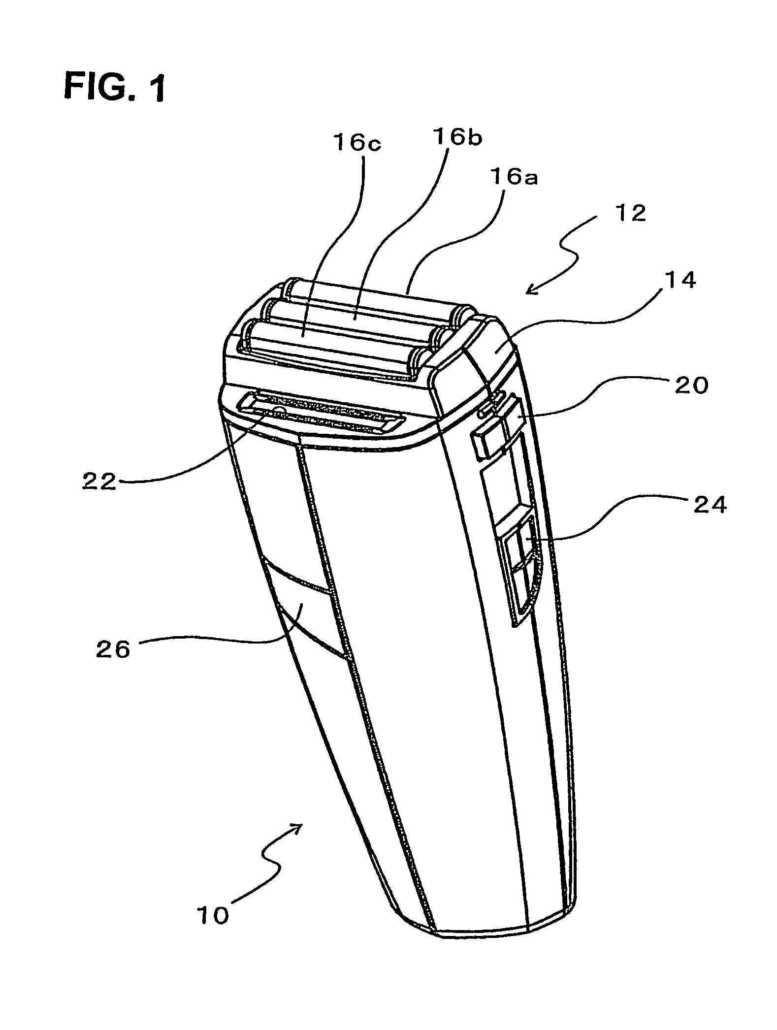
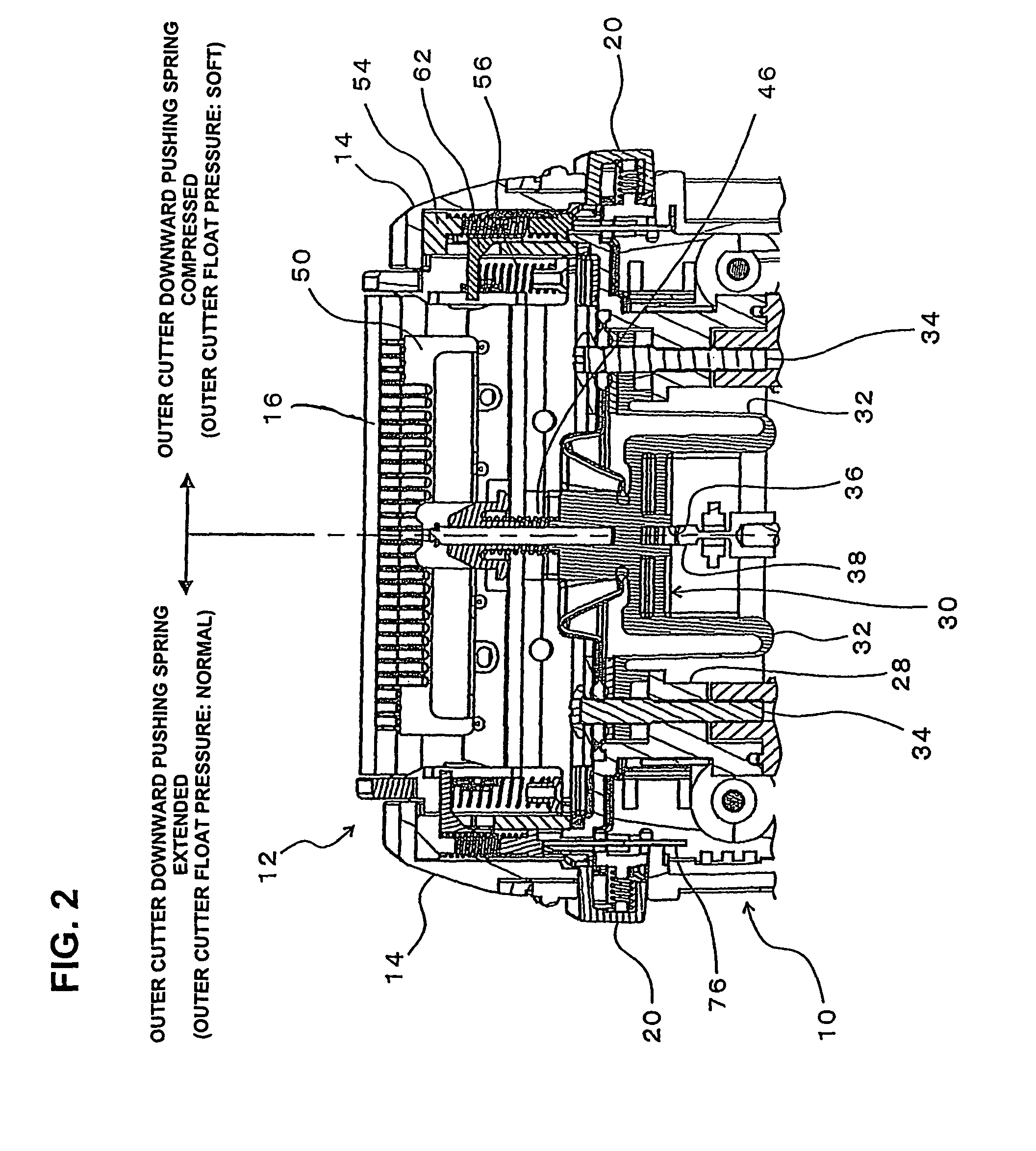
[0036]FIG. 1 is a perspective view of the reciprocating shaver according to one embodiment of the present invention, while FIG. 2 is a vertical section of the shaver head unit of this shaver. In FIG. 2, a condition in which the outer cutter float pressure is made either strong or ordinary (normal) is illustrated on the left half of the drawing, and a condition in which the outer cutter float pressure is made weak (soft) is illustrated on the right half of the drawing. FIG. 3A, a partial view of FIG. 2, shows the situation in which the outer cutter float pressure is made strong (normal), and FIG. 3B, another partial view of FIG. 2, shows the situation in which the outer cutter float pressure is made weak (i.e. soft, corresponding to the right half of FIG. 2). FIG. 4 shows the shaver head unit disassembled, and FIG. 5 shows the detail of a mechanism for adjusting the height of a slide member by a manual manipulator. FIG. 6 is a bottom view of the slide member height adjusting mechanis...


PUM


Abstract

A locking device for securing an attachment member to a main body including first engagement pawls provided in the attachment member so that the first engagement pawls extend in the direction of attachment-detachment of the attachment member and along the inner surface of the main body and a push button assembly secured to the inner surface of the main body. The push button assembly includes a back panel for being secured to an inner surface of the main body, a push button for protruding through an opening in the main body, second engagement pawls formed on the push button and a compression spring provided between the push button and the back panel.

Description

BACKGROUND OF THE INVENTION[0001]1. Field of the Invention[0002]The present invention relates to a locking device for securing an attachment member to a main body and more particularly to a locking device suitable for a reciprocating electric shaver for shaving, for instance, face whiskers (“hair”) by causing an inner cutter(s) to move reciprocally while being pressed against the inner surface of an outer cutter(s) that is substantially inverted-U-shaped when viewed from the side.[0003]2. Description of the Related Art[0004]Reciprocating electric shavers are commonly known. Generally, reciprocating electric shavers are made so that an inner cutter is caused to move reciprocally while it is being pressed against the inner surface of an outer cutter that is substantially inverted-U-shaped when seen from the side, and hair coming through the slits provided in the outer cutter is cut by the reciprocating inner cutter.[0005]Japanese Patent Application Laid-Open (Kokai) Nos. 2004-49864 an...

Claims


Application Information

Patent Timeline
Patent Type & Authority Patents(United States)
IPC IPC(8): B26B19/04A44B99/00
CPCB26B19/3853B26B19/046B26B19/3886B26B19/386B26B19/06Y10T24/45272
Inventor SHIBA, SHINJI
Owner IZUMI PROD CO
Learn More