Armature core of rotating electric machine

a technology of rotating electric machines and armatures, which is applied in the direction of rotating parts of magnetic circuits, magnetic circuits characterised by magnetic materials, and magnetic circuits. it can solve the problems of complex work for fixing individual divided cores to the boss one by one, and the difficulty of forming a space for accommodating joint parts, etc., to achieve the effect of improving assembly work efficiency

Active Publication Date: 2007-02-15
MITSUBISHI ELECTRIC CORP
View PDF6 Cites 9 Cited by
  • Summary
  • Abstract
  • Description
  • Claims
  • Application Information

AI Technical Summary

Benefits of technology

[0010] This structure makes it possible to achieve an improvement in the efficiency of assembly work for fixedly joining separate elements into a single body without requiring difficult machining even when the core size is reduced.

Problems solved by technology

Therefore, in a case where the core is made compact, for example, there has been a problem that it is structurally difficult to form a space for accommodating the joint parts before and after the joint parts are deformed by compression, for instance, and the scope of application of this structure is limited.
Thus, although the scope of application of this structure is not limited, there has been a problem that work for fixing the individual divided cores to the boss one by one is so complex that efficiency of assembly work for fixedly joining the divided cores into a single body decreases in this approach.

Method used


Image

  • Armature core of rotating electric machine
  • Armature core of rotating electric machine
  • Armature core of rotating electric machine

Examples


first embodiment

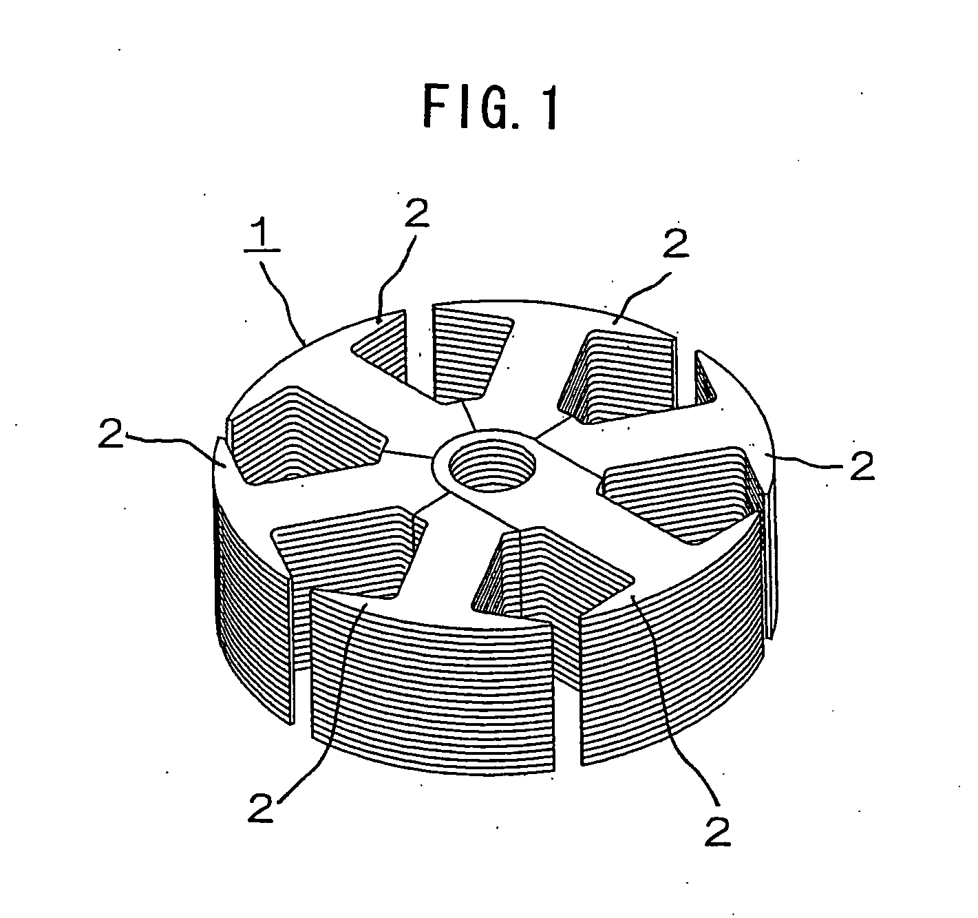
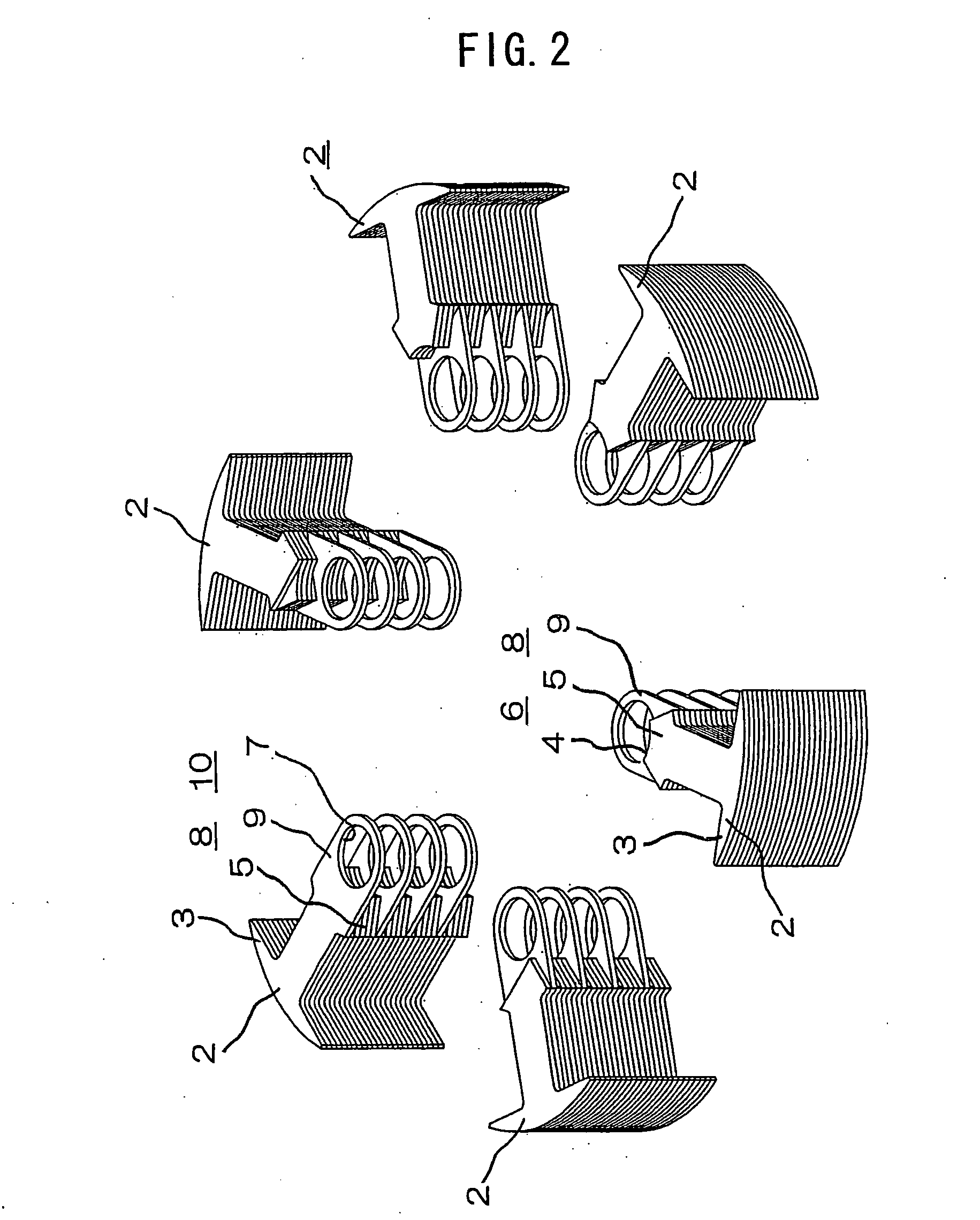
[0025]FIG. 1 is a perspective view showing the structure of an armature core of a rotating electric machine according to a first embodiment of this invention, FIG. 2 is an exploded perspective view showing the rotating electric machine armature core of FIG. 1, FIG. 3 is a perspective view showing a state in which one of magnetic tooth sections of the rotating electric machine armature core of FIG. 1 has been detached, FIG. 4 is a plan view showing the rotating electric machine armature core of FIG. 1, FIG. 5 is a cross-sectional view showing a cross section taken along a line V-V of FIG. 4, FIG. 6 is a diagram showing a process of winding coils on the rotating electric machine armature core of FIG. 1, FIG. 7 is a perspective view showing an example in which the magnetic tooth sections of the rotating electric machine armature core of FIG. 1 have been fixedly combined into a single body by forcibly inserting a rotary shaft, and FIG. 8 is a cross-sectional view showing an example in w...

second embodiment

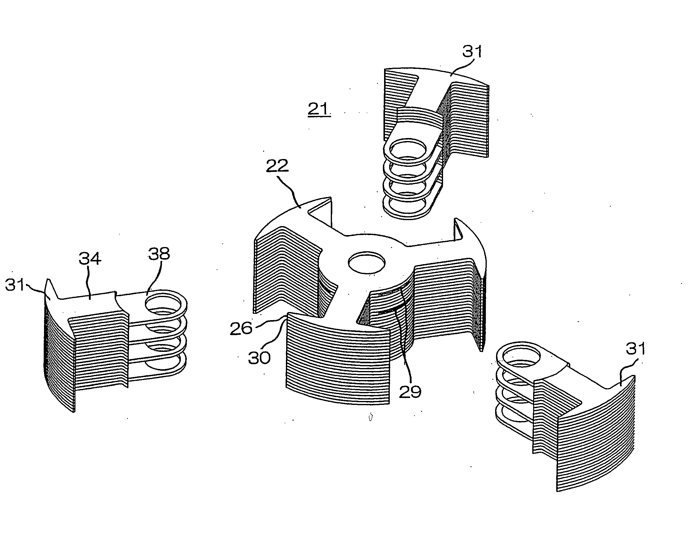
[0033] A rotating electric machine armature core 21 according to a second embodiment of this invention is configured by combining a first magnetic tooth section 22 disposed at a central position and a plurality of second magnetic tooth sections 31 disposed in surrounding areas of the first magnetic tooth section 22 as shown in FIG. 9. FIG. 10 is a fragmentary cross-sectional view showing the structure of a principal part of the rotating electric machine armature core of FIG. 9.

[0034] The first magnetic tooth section 22 is configured by laminating specific numbers of first sheet members 26 and second sheet members 30 as shown in FIG. 11. Each of the first sheet members 26 includes a ringlike portion 24 having a through hole 23 at a central part and a plurality of magnetic tooth portions 25 formed to extend from around this ringlike portion 24 at specific intervals along a circumferential direction. Each of the second sheet members 30 has the second sheet member 30 which includes a s...

third embodiment

[0039]FIG. 13 is a fragmentary cross-sectional view showing the structure of a principal part of a rotating electric machine armature core according to a third embodiment of this invention, in which elements similar to those of the aforementioned first embodiment are designated by the same reference numerals and a description of such elements is omitted.

[0040] The rotating electric machine armature core of the third embodiment of this invention is configured in such a manner that surfaces of individual magnetic tooth sections 2 are covered with molding resin 42 and extreme end parts 43 of a magnetic tooth portion 3 of each magnetic tooth section 2 extend so that a slot opening between extreme ends of one magnetic tooth portion 3 and another is closed. The aforementioned structure makes it possible to decrease windage loss by reducing passage flow resistance of air gaps and thereby increase the efficiency of a rotating electric machine.


PUM


Abstract

A rotating electric machine armature core (1) is configured by combining such a number of magnetic tooth sections (2) that corresponds to the number of magnetic poles, each of the magnetic tooth sections (2) including a plurality of first sheet members (6) each of which includes a magnetic tooth portion (3) formed at one end and a root portion (5) formed at the other end with an end face of the root portion (5) having a prescribed external shape, and at least one second sheet member (10) inserted between the individual first sheet members (6) in a laminating direction thereof at a location different from the locations of the other sheet members, the second sheet member (10) including the magnetic tooth portion (3) formed at one end and an overlapping portion (9) formed at the other end, the overlapping portion (9) forming a back yoke portion (8) together with the root portion (5) with a through hole (7) formed at a specified position in the overlapping portion (9), the overlapping portion (9) jutting out from the root portion (5) in such a manner that the overlapping portion (9) can fit on the end face of the root portion (5) of the first sheet member (6), wherein the magnetic tooth sections (2) are combined in a radial form with the through holes (7) in the individual overlapping portions (9) aligned at the same location.

Description

TECHNICAL FIELD [0001] The present invention relates to an armature core of a rotating electric machine, the armature core having a split structure of which components can be easily joined and fixed together to form a single body. BACKGROUND ART [0002] An example of a conventional rotating electric machine armature core is shown in Japanese Laid-open Patent Application No. 1999-155263, in which the armature core is structured by winding coils around tooth portions of a laminated iron core which is formed by laminating elemental iron core steel sheets having a plurality of tooth portions which are connected by joint parts and arranged in an annular shape, and then fixedly joining the elemental iron core steel sheets to a yoke portion located on an inner peripheral parts or an outer peripheral parts of the tooth portions to form a single body by compressing and deforming the laminated iron core to a predetermined outer diameter from outer peripheral directions thereof. [0003] Another ...

Claims


Application Information

Patent Timeline
Patent Type & Authority Applications(United States)
IPC IPC(8): H02K1/18H02K1/00H02K1/22H02K1/14H02K1/28H02K5/08
CPCH02K1/148H02K15/022H02K5/08H02K1/24H02K1/28
Inventor YAMAMOTO, KAZUYUKIYONEMORI, KEI
Owner MITSUBISHI ELECTRIC CORP
Why Eureka
Try Eureka