Gas-engine-mounted working machine

a working machine and gas engine technology, applied in the direction of tank vehicles, tilling equipment, transportation items, etc., can solve the problems of inconvenient installation, inconvenient installation, and inability to meet the left and right walls of the gas canister cover unit, so as to achieve high rigidity and reduce size and cost

Inactive Publication Date: 2012-03-20
HONDA MOTOR CO LTD
View PDF19 Cites 4 Cited by
  • Summary
  • Abstract
  • Description
  • Claims
  • Application Information

AI Technical Summary

Benefits of technology

[0007]In view of the foregoing prior art problems, it is an object of the present invention to provide an improved gas-engine-mounted working machine which permits reduction in size and cost of the gas canister cover unit, by constructing the gas canister cover unit so that the cover does not have to have a very high rigidity.
[0009]In the present invention arranged in the aforementioned manner, the left and right handle posts can be spaced from the left and right side surfaces, respectively, of the cassette gas canister. Thus, the cassette gas canister can be protected from ambient objects by the left and right handle posts, so that the gas canister cover unit accommodating the cassette gas canister need not have a very high rigidity. As a result, the gas canister cover unit can be significantly simplified in construction and reduced in size.
[0010]In the gas-engine-mounted working machine of the present invention, fuel gas is stored in liquid form in the cassette gas canister, and thus, the cassette gas canister is attached to the gas canister retainer assembly in an upside-down orientation with a gas outlet port of the cassette gas canister oriented downward. Therefore, even when the remaining amount of the liquid fuel gas stored in the cassette gas canister has decreased considerably, the fuel gas can be efficiently led to the outside, e.g. to a nozzle. In this way, the present invention instant embodiment allows the fuel gas to be used up, thereby achieving efficient use of the fuel gas. Normally, the gas canister retainer assembly is located substantially below the waist of a human operator operating the. Thus, the human operator can attach the cassette gas canister, in the upside-down posture or orientation, to the gas canister retainer assembly by just pushing the gas canister into the retainer assembly. Further, when the cassette gas canister is to be detached from the gas canister retainer assembly, the human operator only has to pull the cassette gas canister upward. Therefore, the present invention can facilitate the attachment and detachment of the cassette gas canister to and from the gas canister retainer assembly.
[0011]Preferably, the cassette gas canister has a lead tube of a generally L shape provided therein for leading the fuel gas to the gas outlet port, and the gas canister retainer assembly includes a positioning member for, when the cassette gas canister is to be attached to the gas canister retainer assembly, positioning the cassette gas canister in such a manner that an inlet portion of the lead tube, provided for leading the fuel gas into the lead tube, is located close to a lowermost interior region of the cassette gas canister attached to the gas canister retainer assembly in the upside-down orientation. Therefore, even when the remaining amount of the liquid fuel gas stored in the cassette gas canister has decreased considerably, the fuel gas can be efficiently led to the outside, e.g. to the nozzle. In this way, the present invention instant embodiment allows the fuel gas to be used up even more efficiently.
[0012]Preferably, the positioning member comprises a leaf spring. Thus, the positioning member in the present invention can be of a simplified construction, which can thereby greatly facilitate assemblage or attachment of the cassette gas canister to the gas canister retainer assembly. Upon completion of the assemblage or attachment of the cassette gas canister to the gas canister retainer assembly, the leaf spring comes back to its original shape to engage with the cassette gas canister. In this way, the human operator can confirm that the cassette gas canister has been appropriately positioned in its predetermined attached position, through an abutting sound produced, or an abutting feel transmitted to a hand of the human operator, when the leaf spring has appropriately engaged with the cassette gas canister.
[0013]Preferably, the cassette gas canister has a substantial lower half portion covered with the gas canister cover unit of the retainer assembly. Thus, a substantial upper half portion of the gas canister is allowed to project upward beyond the cover unit, so that the present invention not only can even further facilitate the attachment and detachment of the cassette gas canister, but also allows the human operator to confirm at a glance whether the cassette gas canister is currently attached to the gas canister retainer assembly.

Problems solved by technology

Therefore, during operation of the gas-engine-mounted working machine, ambient obstacles, such as trees or crops, might interfere with left and right walls of the gas canister cover unit.
Further, during storage into a given place, the left and right walls of the gas canister cover unit might undesirably contact and be interfered with by ambient obstacles.

Method used


Image

  • Gas-engine-mounted working machine
  • Gas-engine-mounted working machine
  • Gas-engine-mounted working machine

Examples


Embodiment Construction

[0028]In the following description, the terms “front”, “rear”, “left” and “right” are used to refer to directions as viewed from a human operator. Whereas a walk-behind cultivating machine will hereinafter be described as a preferred embodiment of a gas-engine-mounted working machine of the present invention, the present invention is not limited to such a walk-behind cultivating machine.

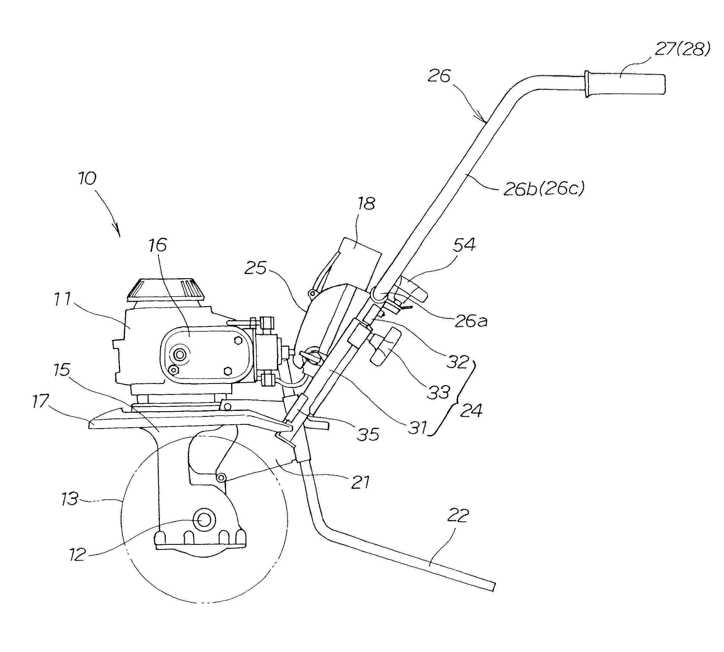
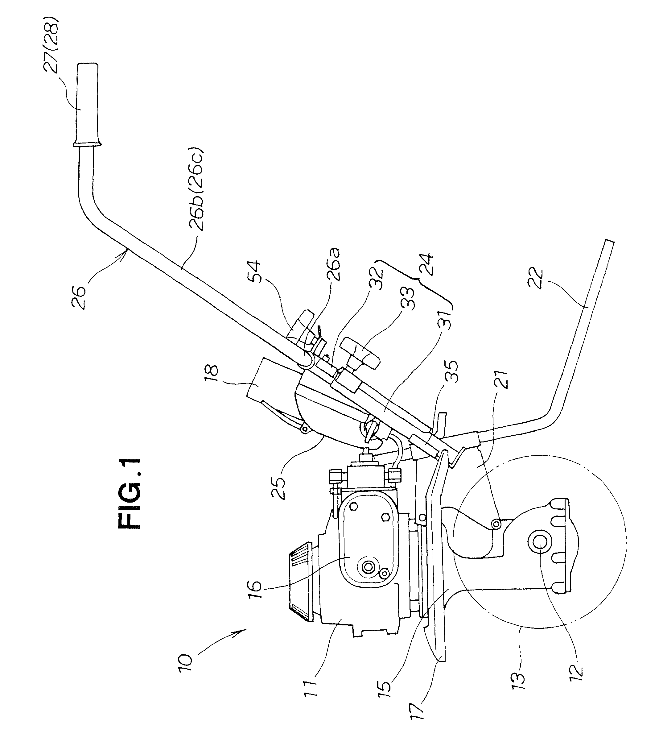
[0029]FIG. 1 is a side view according to an embodiment of the gas-engine-mounted working machine 10 of the present invention. The gas-engine-mounted working machine 10 illustrated here is a walk-behind cultivating machine where driving power of a gas engine 11 is transmitted to a cultivating shaft 12 to rotate the cultivating shaft 12 so that it can travel while cultivating the soil by means of a plurality of cultivating claws 13.

[0030]The gas-engine-mounted working machine 10 includes a gas engine 11 mounted on an upper end portion of a machine body 15, a fender 17 disposed beneath the gas engine 11...


PUM


Abstract

In a gas-engine-mounted working machine, a gas engine is mounted on a machine body and supplied with fuel gas from a cassette gas canister. The cassette gas canister is detachably attached to a gas canister retainer assembly. Handle column extends rearwardly and upwardly from the machine body and having left and right handle posts fixed to the machine body for supporting an operating handle of the machine. The cassette gas canister is mounted, via the gas canister retainer assembly, between the left and right handle posts.

Description

CROSS-REFERENCE TO RELATED APPLICATION[0001]This application claims the priority of Japanese Application No. 2007-302055, filed Nov. 21, 2007, the entire specification, claims and drawings of which are incorporated herewith by reference.FIELD OF THE INVENTION[0002]The present invention relates to gas-engine-mounted working machines including a handle column extending rearwardly and upwardly from the machine body and an operating handle attached to the handle column.BACKGROUND OF THE INVENTION[0003]Among the conventionally-known working machines are ones which include a gas engine mounted on the machine body, a handle column extending rearwardly and upwardly from the machine body and a storage case (hereinafter referred to as “gas canister cover unit”) provided along a handle post, and in which a cassette gas canister is attached to and accommodated in the gas canister cover unit. One example of such working machines is disclosed in Japanese Patent Application Laid-Open Publication N...

Claims


Application Information

Patent Timeline
Patent Type & Authority Patents(United States)
IPC IPC(8): B60P3/22B60K15/10
CPCA01B33/028B60K15/07
Inventor KOBAYASHI, HIDEAKISASAOKA, MASAYUKI
Owner HONDA MOTOR CO LTD
Why Eureka
Try Eureka