
Tibial knee component with a mobile bearing

a mobile bearing and tibial knee technology, applied in the field of orthopaedics, can solve the problems of undesirably high risk of bearing dislocation or “spinout”, undesirably impinging, and reducing the amount of space available for inserting, aligning and securing the prosthesis

Active Publication Date: 2012-03-20
ZIMMER INC
View PDF58 Cites 106 Cited by
  • Summary
  • Abstract
  • Description
  • Claims
  • Application Information

AI Technical Summary

Benefits of technology

The present invention is a mobile bearing knee prosthesis apparatus that includes a tibial plate and a tibio-femoral insert. The apparatus allows for movement of the insert relative to the plate about an axis medially disposed from the dividing plane. The invention also includes features such as a dividing plane and a stud-like protuberance with eccentric convex arcuate portions. The technical effects of the invention include improved stability, reduced wear, and improved range of motion.

Problems solved by technology

Additionally, the risk of bearing dislocation or “spinout” may be undesirably high for some mobile bearing designs that do not incorporate stops to limit the rotation of the tibio-femoral insert; and the posterior cruciate ligament (“PCL”), when saved, may be undesirably impinged by posterior surfaces of some mobile bearing designs.
As minimally invasive surgery generally reduces the size of the surgical site, it also generally reduces the amount of space available for inserting, aligning, and securing the prosthetics.
The substantial exposures and separations of the distal femur and the proximal tibia required for some such “overhead” tibio-femoral insert installations are becoming increasingly incompatible with the space constraints of minimally invasive surgery.

Method used


Image

  • Tibial knee component with a mobile bearing
  • Tibial knee component with a mobile bearing
  • Tibial knee component with a mobile bearing

Examples


Embodiment Construction

)

[0032]Like reference numerals refer to like parts throughout the following description and the accompanying drawings. As used herein, the terms “medial,”“medially,” and the like mean pertaining to the middle, in or toward the middle, and / or nearer to the middle of the body when standing upright. Conversely, the terms “lateral,”“laterally,” and the like are used herein as opposed to medial. For example, the medial side of the knee is the side closest to the other knee and the closest sides of the knees are medially facing, whereas the lateral side of the knee is the outside of the knee and is laterally facing. Further, as used herein the term “superior” means closer to the top of the head and / or farther from the bottom of the feet when standing upright. Conversely, the term “inferior” is used herein as opposed to superior. For example, the heart is superior to the stomach and the superior surface of the tongue rests against the palate, whereas the stomach is inferior to the heart an...


PUM


Abstract

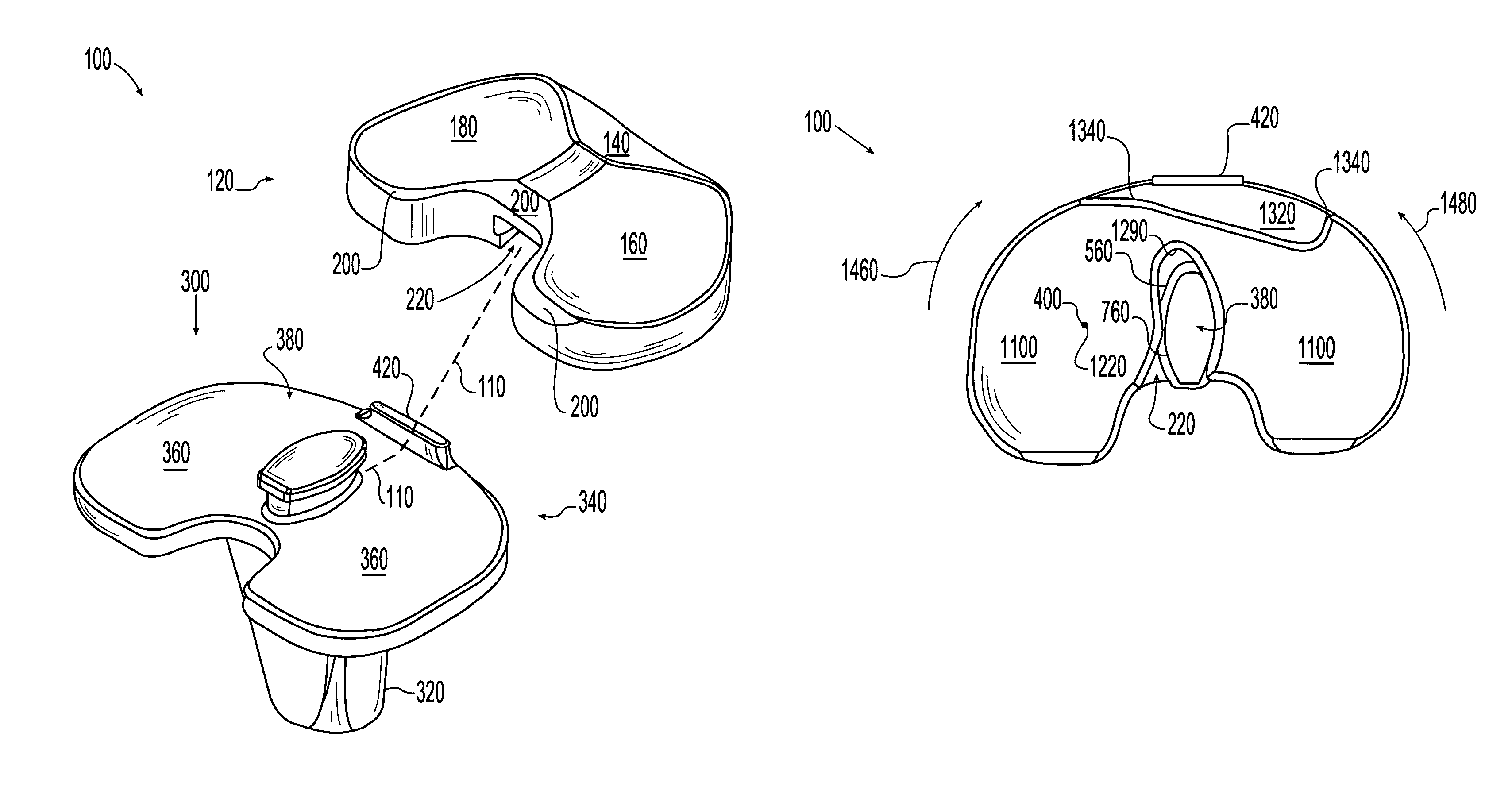
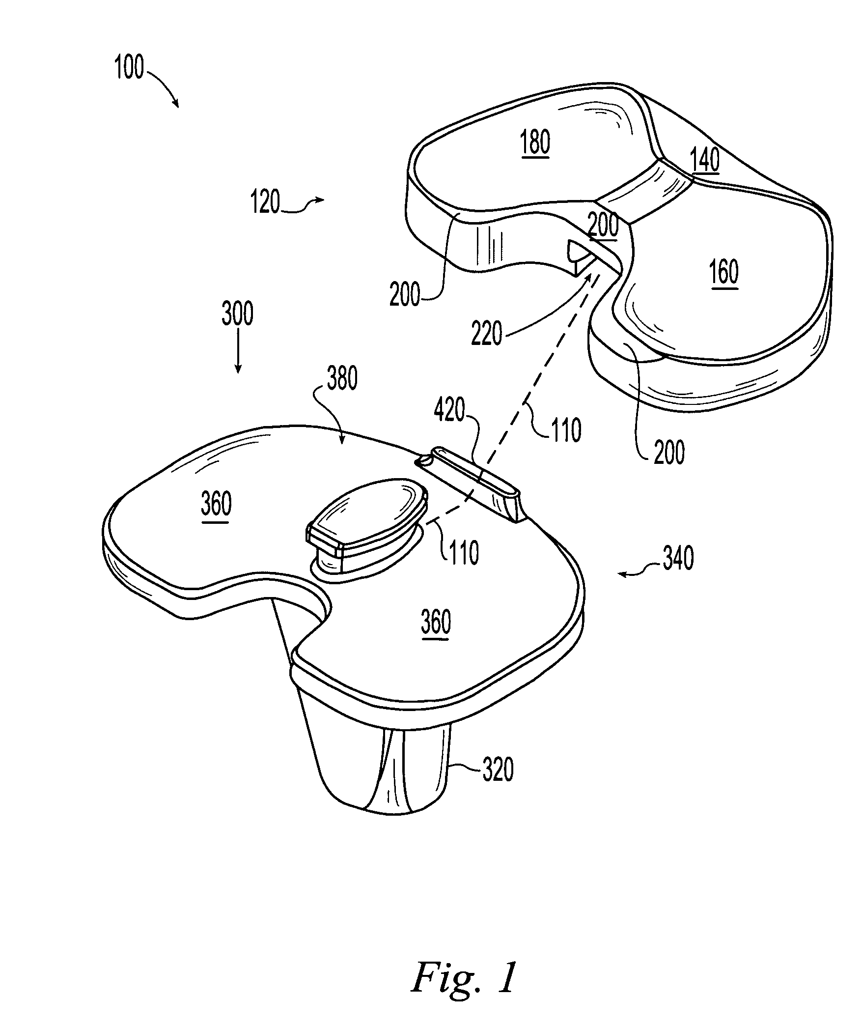
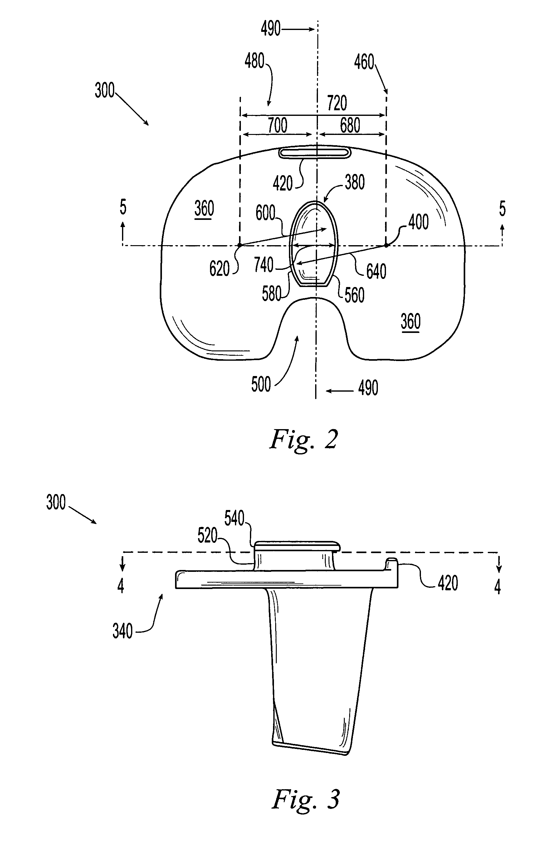
A mobile bearing knee prosthesis apparatus includes a tibial plate. The tibial plate includes a medial lobe and a lateral lobe conjoined in a dividing plane. The apparatus further includes a tibio-femoral insert and a stud-like protuberance extending from the tibial plate into the tibio-femoral insert. The stud-like protuberance includes a protuberance sidewall positioned in the tibio-femoral insert. The protuberance sidewall is bisected by the dividing plane and includes a pair of opposing eccentric convex arcuate portions, and the tibio-femoral insert is moveable relative to the tibial plate about an axis medially disposed from the dividing plane. A mobile bearing knee prosthesis apparatus includes a tibial plate and a tibio-femoral insert coupled to the tibial plate. The tibio-femoral insert includes a generally posteriorly positioned chamfered superior surface and defines a generally posteriorly positioned generally U-shaped space bounded at least in part by the chamfered surface.

Description

CROSS-REFERENCE TO RELATED APPLICATION(S)[0001]This application claims the benefit of U.S. Provisional Patent Application Ser. No. 60 / 552,104, filed Mar. 9, 2004, entitled “MEDIAL AXIS MOBILE BEARING KNEE PROSTHESIS,” which is expressly incorporated herein by reference.FIELD OF THE INVENTION[0002]The present invention relates generally to the field of orthopaedics, and, more particularly, to a mobile bearing knee prosthesis apparatus.BACKGROUND[0003]Total joint arthroplasty (“joint replacement”) is the surgical replacement of a joint with a prosthesis. A typical knee prosthesis has three main components: a femoral implant, a tibial implant, and a tibio-femoral insert. In general, the femoral implant is designed to replace the distal femoral condyles. The femoral implant is typically made from metal. It typically includes a generally concave, facetted (i.e., piecewise planar) inwardly facing surface defining a cavity for receiving a resected distal femur and typically further include...

Claims


Application Information

Patent Timeline
Patent Type & Authority Patents(United States)
IPC IPC(8): A61F2/38
CPCA61F2/3868
Inventor TODD, DWIGHT T.BYRD, BRIAN D.HARRIS, JAMES C.BERTIN, KIM C.TANAMAL, LINGGAWATIWALKER
Owner ZIMMER INC
Learn More