Thermal printer

a printer and thermal technology, applied in the field of thermal printers, can solve the problems of difficult positioning, paper transportation load, and inability to print optimally on only one side, and achieve the effect of convenient configuration

Active Publication Date: 2012-03-20
SEIKO EPSON CORP
View PDF11 Cites 4 Cited by
  • Summary
  • Abstract
  • Description
  • Claims
  • Application Information

AI Technical Summary

Benefits of technology

[0014]A thermal printer according to at least one embodiment of the invention has a first platen roller or first thermal print head mounted on a first arm, and a second thermal print head or second platen roller mounted on a second arm. Two thermal print head and platen roller sets can be opened and closed by opening and closing these two arms. Positioning the parts is therefore simpler and more precise than a configuration in which one of the parts for two thermal print head and platen roller sets are mounted on a single arm. In addition, because little force is applied to each arm when closing the arms, the arms are prevented from latching closed on only one side.
[0018]If the second arm on which the second thermal print head or the second platen roller located on the upstream side in the thermal paper transportation path reaches the closed position first, the thermal paper can be prevented from being held with slack between the two thermal print head and platen roller sets. If the first arm is closed while pulling the thermal paper to the downstream side in the transportation direction, for example, the second arm will close first and hold the thermal paper between the upstream thermal print head and platen roller so that when the first arm then closes while tension is applied to the thermal print head leader, the thermal paper will be held between the downstream side thermal print head and platen roller with no slack in the paper. The thermal paper can therefore be loaded for printing with no slack. A paper feed operation for removing slack is therefore not necessary, and the thermal paper can be conveyed without skewing caused by slack.
[0020]If the second arm can be set so that it will not reach the second closed position regardless of the position of the first arm when printing on only one side of the thermal paper using only the first thermal print head and first platen roller mounted on the first arm and printer frame, the thermal paper will not be held with the predetermined pressure between the second thermal print head and second platen roller that are not being used. If the second platen roller is moved to the retracted position so that it does not contact the second thermal print head, the thermal paper will also not be held therebetween with the predetermined pressure. Unnecessary paper transportation load can therefore be reduced and high speed printing can be enabled.
[0030]The double-sided thermal printer according to at least one embodiment of the invention can also be easily configured for double-sided or duplex printing and single-sided or simplex printing.

Problems solved by technology

First, when the first arm closes to the second arm, the first print head and first platen carried on the first arm are simultaneously pressed to the respectively opposing second platen and second print head. As a result, even if the first arm is closed while pulling on the double-sided thermal paper so that there is no slack, the first and second platens which are free at this time may rotate due to the tension of the double-sided thermal paper because the double-sided thermal paper is simultaneously held between the first print head and the second platen on the upstream side and the second print head and first platen on the downstream side, and slack results easily between the first and second platens. If slack develops, the double-sided thermal paper may become skewed while being conveyed. An operation to remove the slack is therefore necessary.
Second, the first print head and first platen on the first arm must be positioned to contact the second platen and second print head on the second arm during printer assembly, for example. This requires simultaneously positioning the two print head and platen sets, which makes positioning more difficult than when the first print head is positioned to the second platen and the first platen is separately and independently positioned to the second print head.
Third, because there are two sets of print heads and platens, repulsion to the pressure applied to press the first print head to the second platen and repulsion to the pressure applied to press the second print head to the first platen both work when the first arm closes. This requires applying twice as much force to the first arm as when there is only one print head and platen set and a single print head is pressed to the platen. A strong operating force is therefore required to overcome twice the repulsion force when closing the first arm, and the first arm can be easily deformed by this strong operating force. When the cover to which the first arm is attached is closed to the printer frame side and an assembly that latches at both widthwise sides are used, deformation of the first arm when the cover closes can result in only one side engaging in the closed position and the other side not completely engaging in the closed position. The possibility is therefore high that the cover may be latched on only one side.
Fourth, because two sets of print heads are always pressed against the opposing platens when the first arm is closed, the paper transportation load on the double-sided thermal paper passing therebetween is increased. Two sets of print heads are also always pressed against the double-sided thermal paper in the same way as when both sides are printed even if only one side of the paper is printed using one print head similarly to when single-sided thermal paper having a thermo-sensitive coating rendered on only one side of the thermal paper is printed. This creates the problem that printing in a manner that is optimal for printing on only one side is not possible.

Method used


Image

  • Thermal printer
  • Thermal printer
  • Thermal printer

Examples


Embodiment Construction

[0037]Preferred embodiments of a thermal printer according to at least one embodiment of the invention are described below with reference to the accompanying figures.

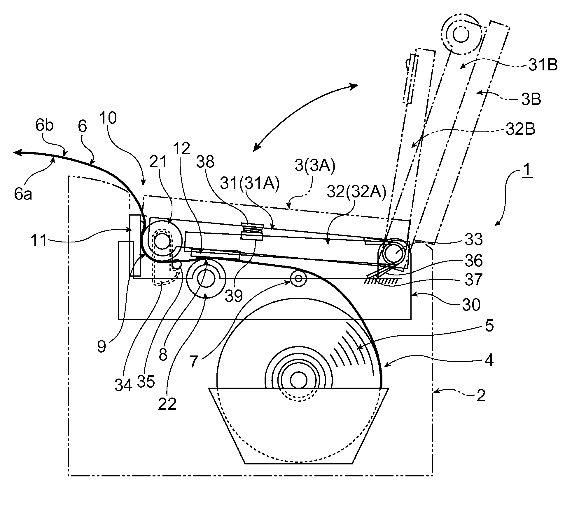
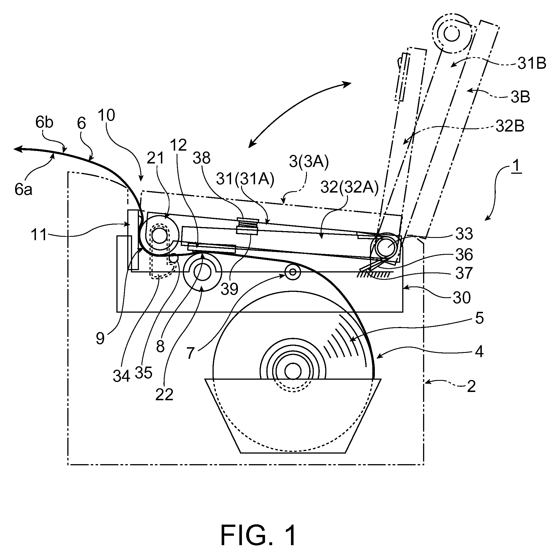
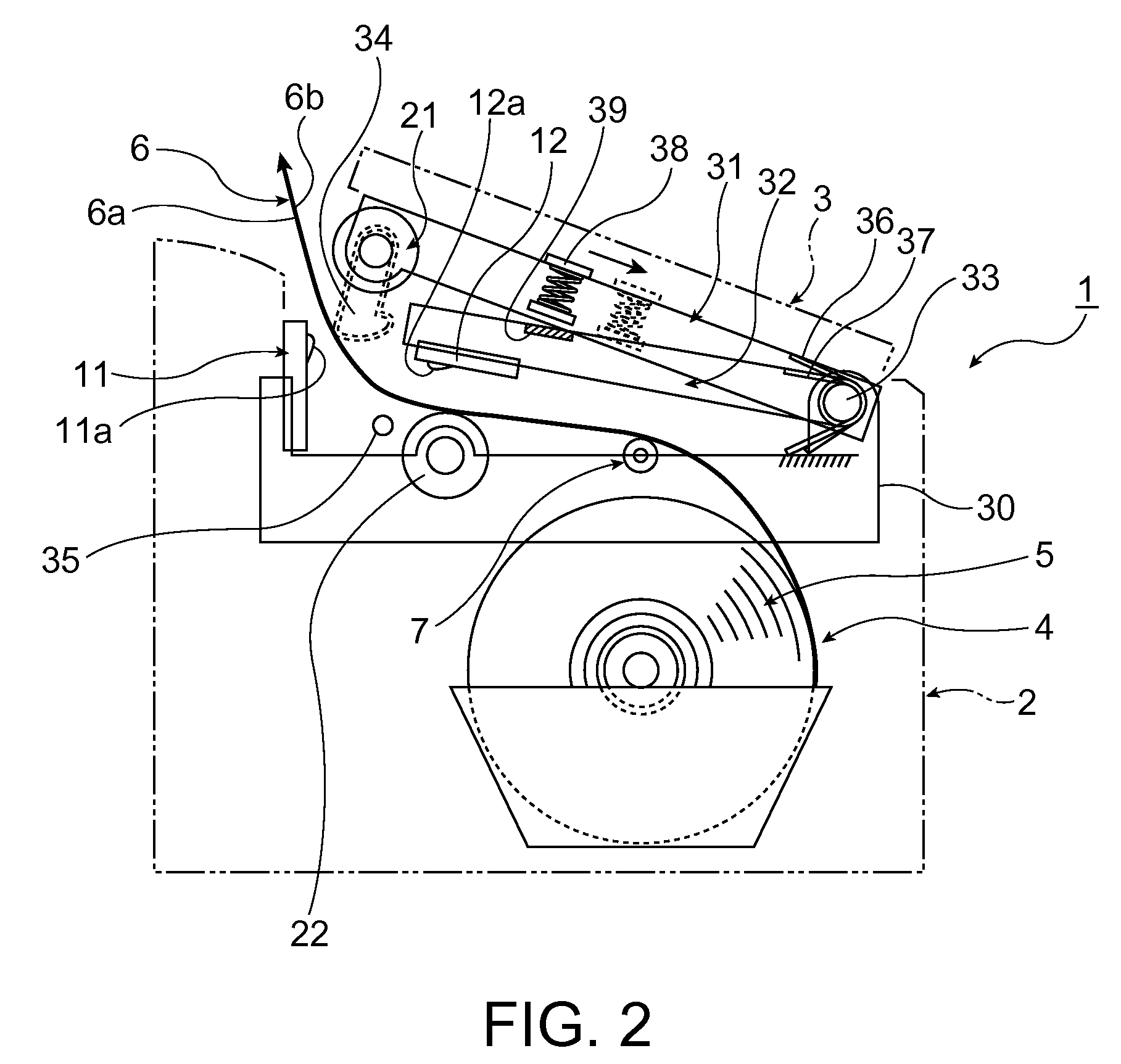
[0038]FIG. 1 describes a double-sided thermal printer according to a preferred embodiment of at least one embodiment of the invention, and FIG. 2 shows the double-sided thermal printer when the operating cover is slightly open.

[0039]The double-sided thermal printer 1 has a basically rectangular box-shaped printer case 2, and an operating cover 3 that is attached to open and close to this printer case 2. The operating cover 3 can open and close between a substantially horizontal closed position 3A and an open position 3B where the operating cover 3 is standing up as indicated by the double-dot dash line in FIG. 1.

[0040]When the operating cover 3 is open, the top end part of the roll paper storage compartment 4 formed inside the printer case 2 is open, and roll paper 5 can be loaded from above into the roll paper storage ...


PUM


Abstract

A thermal printer enables both duplex printing and simplex printing. A double-sided thermal printer 1 has a first arm 31 and a second arm 32 that opens and closes in conjunction with the first arm 31. A first platen roller 21 is mounted on the first arm 31, a second thermal print head 12 is mounted on the second arm 32, and a first thermal print head 11 and second platen roller 22 are disposed on the printer frame 30 side. When the operating cover 3 closes, the second thermal print head 12 on the second arm 32 is pressed against the second platen roller 22, the first platen roller 21 on the first arm 31 is pressed to the first thermal print head 11, and the double-sided thermal paper 6 can be set with no slack. For simplex printing, the paper transportation load can be reduced by pressing only the first platen roller 21 on the first arm to the first thermal print head 11.

Description

CROSS-REFERENCE TO RELATED APPLICATIONS[0001]Japanese Patent application No. 2007-254266 is hereby incorporated by reference in its entirety.BACKGROUND[0002]1. Field of Invention[0003]The present invention relates to a thermal printer having two thermal print head and platen roller sets disposed along the thermal paper transportation path for printing on both the front and back sides of double-sided thermal paper.[0004]2. Description of Related Art[0005]A thermal printer that prints on double-sided thermal paper having thermo-sensitive surfaces formed on both sides of the paper is disclosed in U.S. Pat. No. 6,784,906. The disclosed thermal printer has a first print head and first platen supported on a first arm and a second platen opposing the first print head and a second print head opposing the first platen supported on a second arm installed on the printer frame side. When roll paper is pulled from a roll of double-sided thermal paper and the first arm is closed to the second arm...

Claims


Application Information

Patent Timeline
Patent Type & Authority Patents(United States)
IPC IPC(8): B41J25/304
CPCB41J2/32B41J3/60B41J15/042B41J2202/31B41J2/315B41J2/33
Inventor KOYABU, AKIRATAKAMI, TORUMURATA, SADAOISHINO, HITOSHI
Owner SEIKO EPSON CORP
Why Eureka
Try Eureka