
Field shaping device for radiation therapy

a radiation therapy and field shaping technology, applied in the field of radiation therapy, to achieve the effect of more accurate electron radiotherapy, simple and more precise, and accurate field shaping

Active Publication Date: 2020-09-17
THE BOARD OF TRUSTEES OF THE LELAND STANFORD JUNIOR UNIV
View PDF1 Cites 0 Cited by
  • Summary
  • Abstract
  • Description
  • Claims
  • Application Information

AI Technical Summary

Benefits of technology

The current invention provides better ways to make a device that shapes radiation beams. This new method is simpler and more accurate than previous methods. It also avoids using toxic materials and ensures the device performs well in real-life situations. Overall, this new method is a big improvement over traditional methods, making radiation therapy more effective and cost-efficient.

Problems solved by technology

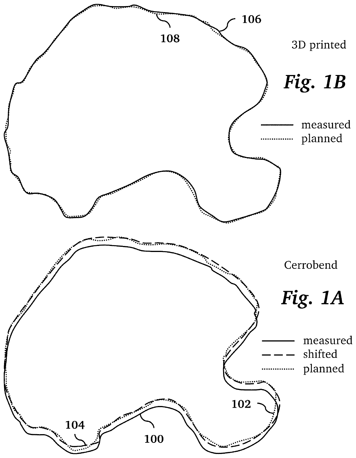
Although 3D printed techniques have been used previously in the process of making customized field shaping devices, their use has been limited to creating a temporary mold to be used only in a molding process, after which the 3D printed mold is discarded, resulting in an end product composed of a single solid metal or solid metal composite field shaping device.

Method used


Image

  • Field shaping device for radiation therapy
  • Field shaping device for radiation therapy
  • Field shaping device for radiation therapy

Examples


Embodiment Construction

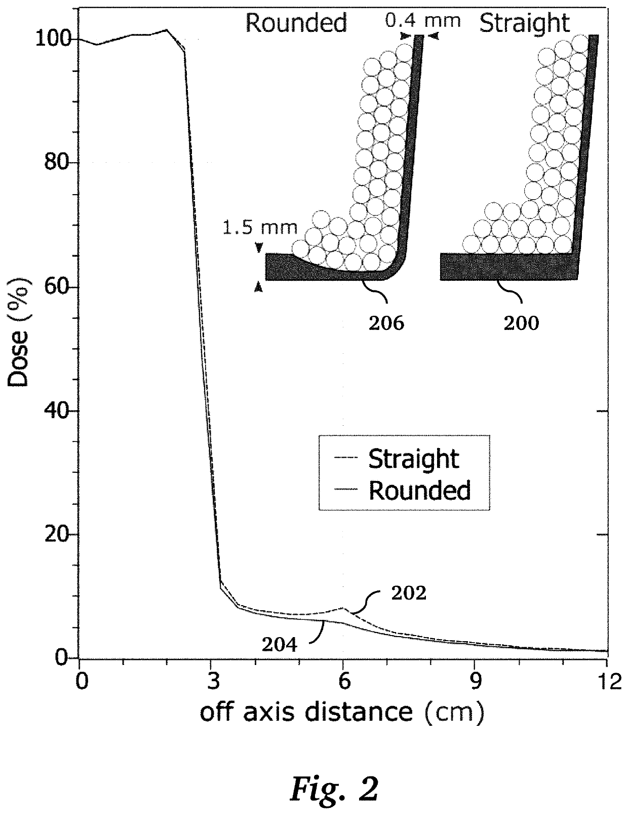
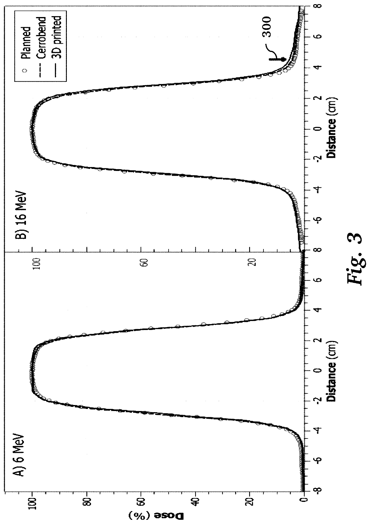
[0022]FIG. 4 shows an electron field shaping device and workflow for making such a device, according to an embodiment of the invention. First, the field outline 400 is exported from a treatment planning system and converted into a 2D vector image 402. The 2D outline is then imported in to CAD software and extruded into a 3D wall 404 using a 3D printer. Divergence and edge rounding fillets are also included in this step. The field edge wall 404 is then combined with a 3D printed template outline that has a corresponding hole 410 in its bottom surface 408. The template also has outer walls 406. Thus, the finished frame has a bottom 408, outer side walls 406, an opening 410 in the bottom 408, and inner walls 404 around the opening in the bottom. The outer side walls, bottom, and inner side walls define an interior space of the frame enclosed on all sides except the top. In preferred implementations, the inner side walls are between 0.2 mm and 5 mm thick and between 5 mm and 30 mm tall....


PUM

PropertyMeasurementUnit
sizeaaaaaaaaaa
sizeaaaaaaaaaa
densityaaaaaaaaaa

Abstract

A radiation beam field shaping device is made from a 3D printed frame that contains and gives shape to a granular material with bulk density of at least 3 g / cm3 and composed of metal grains having a size between 1 μm and 4 mm. The frame has a hole in the bottom with surrounding walls that defines the desired beam shape. In one implementation, the metal grains are composed of solid tungsten alloy ball bearings and / or tungsten alloy powder.

Description

CROSS-REFERENCE TO RELATED APPLICATIONS[0001]This application claims priority from U.S. Provisional Patent Application 62 / 816,599 filed Mar. 11, 2019, which is incorporated herein by reference.FIELD OF THE INVENTION[0002]The present invention relates generally to radiotherapy. More specifically, the invention relates to radiation shielding devices for shaping the field in radiation beams.BACKGROUND OF THE INVENTION[0003]Electron beam radiotherapy delivers a beam into a field of view to irradiate a tumor. To avoid harming healthy tissue, it is desirable to restrict the radiation beam to a specific region of tissue where the tumor is located. This is accomplished by modifying the beam shape using radiation shielding devices, also called field shaping devices. Because the tumor shape and size for each patient is unique, shielding devices with patient-specific shapes are cast into customized molds in accordance with an outline specified by a treatment planning system (TPS). Once molded,...

Claims


Application Information

Patent Timeline
Patent Type & Authority Applications(United States)
IPC IPC(8): B22F3/00B29C64/141B33Y50/00B33Y80/00B33Y10/00B33Y70/00A61N5/10B22F1/00
CPCA61N5/10B29C64/141B33Y70/00B33Y50/00B33Y80/00B33Y10/00A61N2005/1094B22F3/008A61N2005/1095B22F5/10Y02P10/25B22F10/18B22F10/22B22F10/28B22F10/12B22F1/00B22F10/10
Inventor YU, SHU-JUNGSKINNER, LAWRIE BASILFAHIMIAN, BENJAMIN POOYA
Owner THE BOARD OF TRUSTEES OF THE LELAND STANFORD JUNIOR UNIV
Learn More