Method for controlling energy in the traction chain of a hybrid vehicle and hybrid vehicle

a technology of hybrid vehicles and traction chains, which is applied in the direction of propulsion parts, propulsion using engine-driven generators, process and machine control, etc., can solve the problems of imprecise results, and achieve the effect of optimizing fuel consumption and preserving the useful life of electrical energy storage means

Active Publication Date: 2012-04-10
PEZHO SITROEN AUTOMOBILS SA
View PDF10 Cites 2 Cited by
  • Summary
  • Abstract
  • Description
  • Claims
  • Application Information

AI Technical Summary

Benefits of technology

[0016]Besides optimizing fuel consumption, the method according to the invent

Problems solved by technology

Using the engine efficiency to calculate the fuel consumption of the heat engine yields

Method used


Image

  • Method for controlling energy in the traction chain of a hybrid vehicle and hybrid vehicle
  • Method for controlling energy in the traction chain of a hybrid vehicle and hybrid vehicle
  • Method for controlling energy in the traction chain of a hybrid vehicle and hybrid vehicle

Examples


Embodiment Construction

[0034]In the figures, the same references are used to designate the same elements.

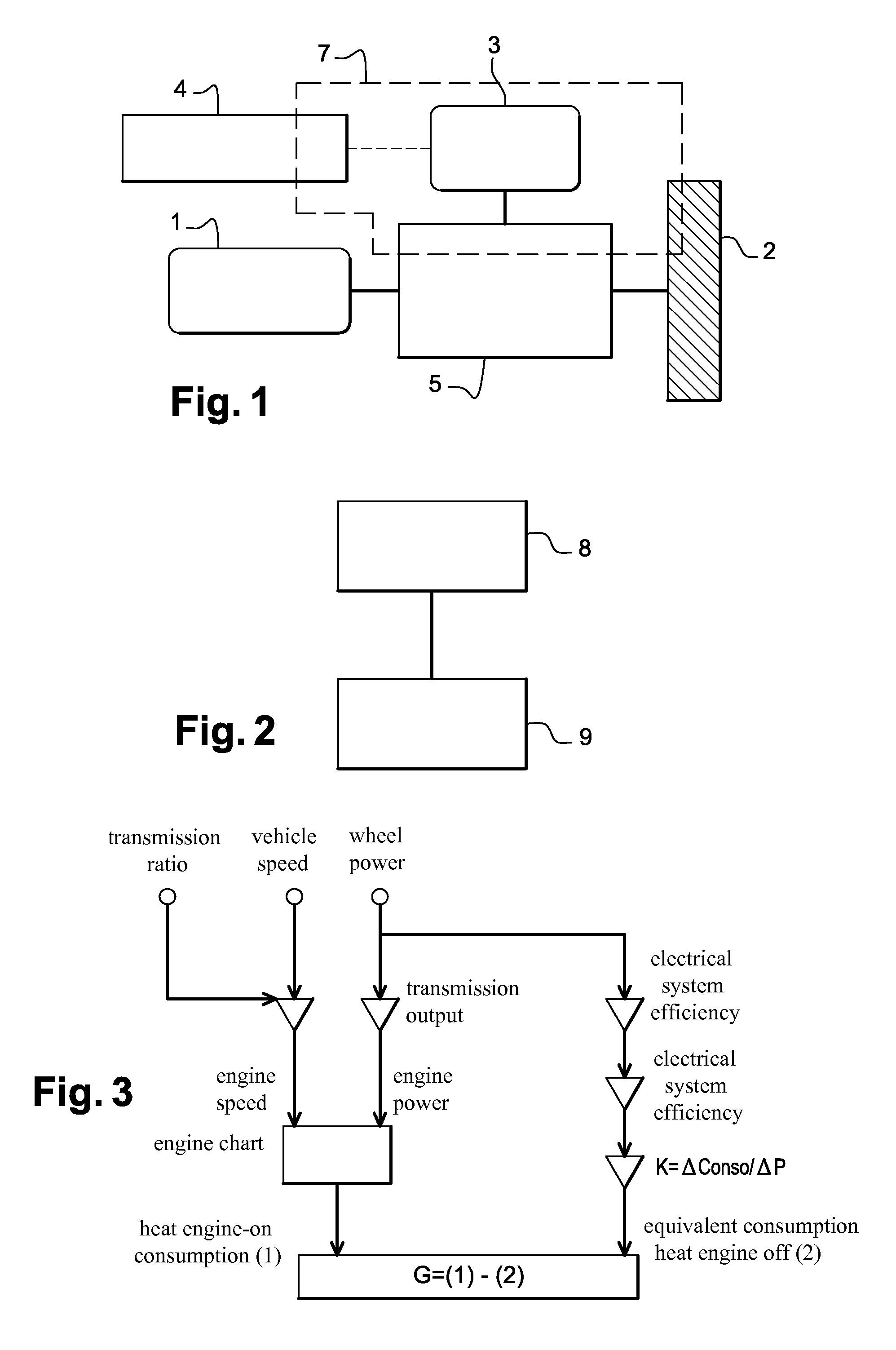
[0035]The method according to the invention is illustrated by the flowchart in FIG. 2.

[0036]It consists of, in a first step 8, determining the fuel consumption gain of the heat engine, and then, in a second step 9, deciding to turn the heat engine on or off based on a preset criterion and the fuel consumption gain.

[0037]The first step 8 is illustrated by the block diagram in FIG. 3.

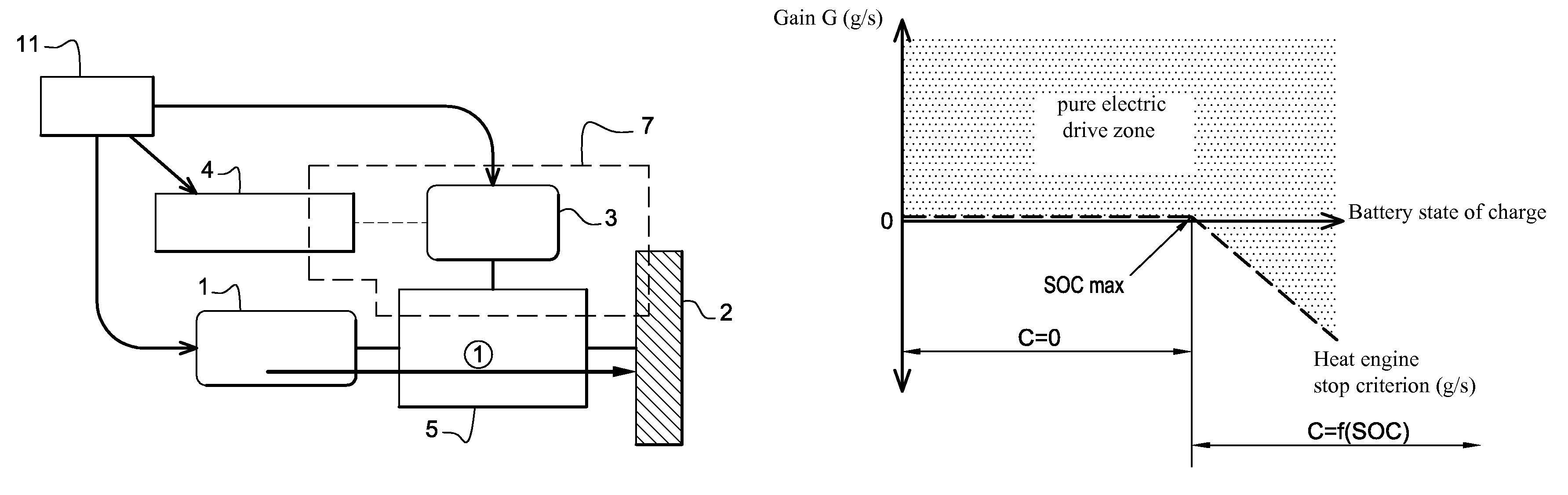
[0038]This first step is based on calculating the potential fuel consumption gain G associated with stopping the heat engine at a given moment of travel. Calculating this gain in real time and comparing the result of this calculation to a set coefficient determines whether the heat engine has to remain on or be turned off.

[0039]The way to calculate this gain G is described below.

[0040]In this first step 8, neither energy recovery nor energy sources outside the heat engine are considered. The only source of energy considered ...


PUM


Abstract

The method includes, during a first step (8) determining in real time the fuel consumption gain of the thermal engine by defining the difference between the consumption of the thermal engine in operation and the consumption of the thermal engine when stopped independently from other energy sources outside the thermal engine, the equivalent consumption being calculated from a predetermined coefficient corresponding to the ratio between a consumption difference and an engine power difference for a given engine speed; during a second step (9), deciding to switch on or switch off the thermal engine according to a criterion and to the consumption gain, the criterion depending on the recovery level of the electric energy recovering means and being determined in order to increase the use of the electric energy storage means and to switch off the thermal engine as often as possible.

Description

BACKGROUND ART[0001]The invention relates to strategies for managing the energy sources involved in powering (combustion / electric) hybrid vehicles.[0002]More particularly, it relates to an energy management method for a hybrid vehicle drive system, the purpose of which is to minimize fuel consumption and preserve the useful life of the electrical energy storage means.[0003]A hybrid drive system is schematically illustrated in FIG. 1.[0004]Such a drive system typically comprises a heat engine 1 supplying mechanical energy to the vehicle drive wheels 2 (just one wheel is shown), one or more electric machines 3 (just one electric machine is shown) supplying electrical energy to the vehicle wheels 2, means for storing electrical energy 4, means 5 for transmitting mechanical and electrical energy to the vehicle wheels 2, and electrical energy recovery means 7 shown enclosed by a dashed line.[0005]One of the possible energy recovery means, also described as “natural”, is for example to us...

Claims


Application Information

Patent Timeline
IPC IPC(8): B60K6/24
CPCB60K6/48B60W10/06B60W10/08B60W10/26B60W20/00B60L11/14B60L11/1861B60L15/20B60L15/2045Y10S903/93B60W2510/244Y02T10/52Y02T10/6221Y02T10/6286Y02T10/642Y02T10/92B60L2240/12B60L2240/80B60L2240/423Y02T10/70Y02T10/72B60L50/16B60L58/12Y02T10/40Y02T10/62Y02T10/64Y02T10/7072B60W2710/083B60W20/10
Inventor JUNCA, CARLOSMULOT, VINCENT
Owner PEZHO SITROEN AUTOMOBILS SA
Why Eureka
Try Eureka