Control apparatus and process for internal combustion engine

a technology of control apparatus and process, which is applied in the direction of electric control, instruments, road transportation, etc., can solve the problems of deteriorating fuel consumption, reducing the effect of exhaust gas recirculation, and reducing the acceleration response of the vehicle, so as to reduce the effect and improve the fuel consumption

Active Publication Date: 2005-08-04
NISSAN MOTOR CO LTD
View PDF7 Cites 48 Cited by
  • Summary
  • Abstract
  • Description
  • Claims
  • Application Information

AI Technical Summary

Benefits of technology

[0004] However, the limitation of the exhaust gas recirculation during acceleration reduces the effect of exhaust gas recirculation significantly if the exhaust gas recirculation is limited without regard to the engine operating point at that time. In order to improve the fuel consumption, it is desirable to perform the exhaust gas recirculation as much as possible even during acceleration.
[0006] It is an object of the present invention to provide control apparatus or process to decrease the exhaust gas recirculation more effectively in accordance with an engine operating condition.

Problems solved by technology

However, the limitation of the exhaust gas recirculation during acceleration reduces the effect of exhaust gas recirculation significantly if the exhaust gas recirculation is limited without regard to the engine operating point at that time.
If, on the other hand, the exhaust gas recirculation is performed during acceleration in the same manner as in the steady state, the exhaust gas recirculation tends to deteriorate the acceleration response of the vehicle, and even deteriorates the fuel consumption.
If the exhaust gas recirculation is continued in a normal mode at the time of driver's depression of the accelerator pedal, the rise of engine torque is slow, and the driver is liable to further depress the accelerator pedal unconsciously, so that the engine operating point enters a high load region detrimental to the fuel economy.

Method used


Image

  • Control apparatus and process for internal combustion engine
  • Control apparatus and process for internal combustion engine
  • Control apparatus and process for internal combustion engine

Examples


first embodiment

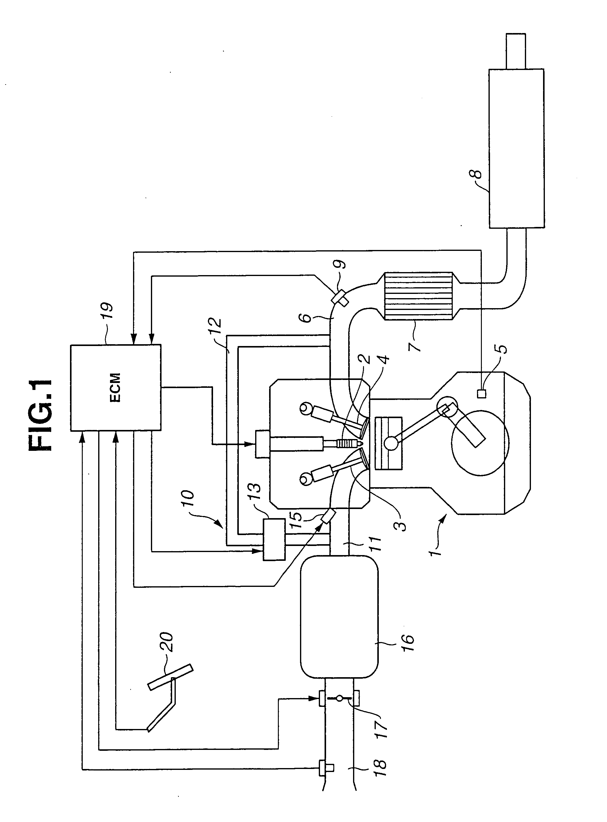
[0032]FIG. 1 shows a control apparatus or system according to the present invention. An internal combustion engine 1 of this example is a spark ignition engine having a spark plug 2 located at the center of a combustion chamber, and intake and exhaust valves 3 and 4 for each cylinder. A crank angle sensor 5 is arranged to sense the rotation of a crankshaft of the engine.

[0033] In an exhaust passage 6, there are provided a catalytic converter 7 and a muffler 8. At a position upstream of catalytic converter 7, there is provided an air fuel ratio sensor 9 for sensing an exhaust air fuel ratio.

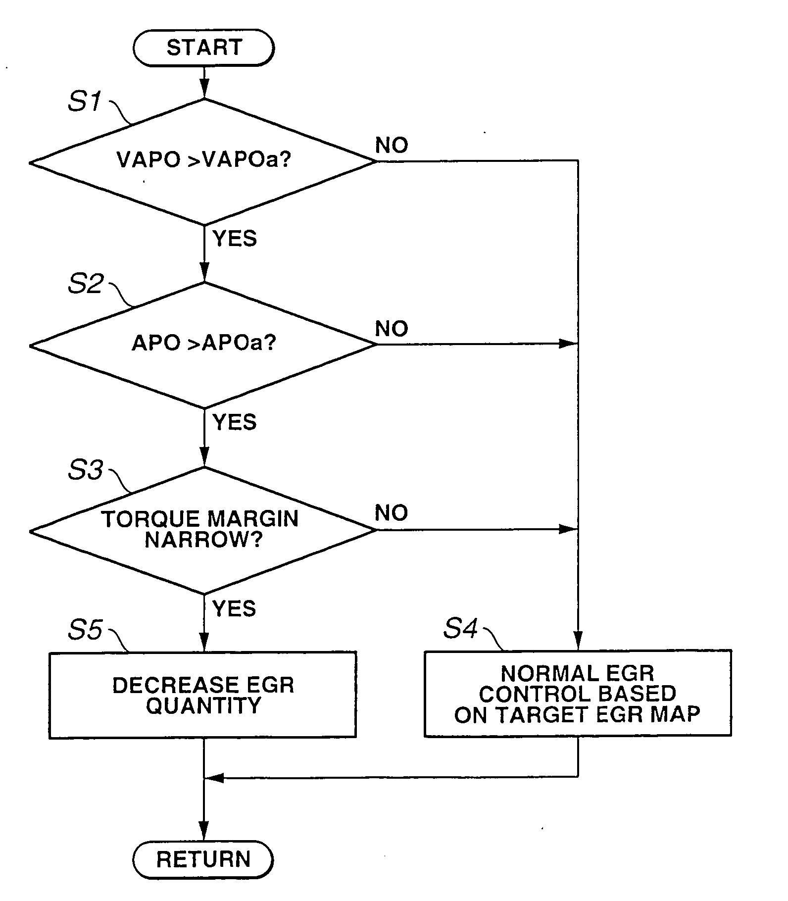
[0034] An exhaust gas recirculation system or apparatus 10 of this example includes an exhaust gas recirculation passage (EGR passage) 12 extending from exhaust passage 6 to an intake passage 11, and an exhaust gas recirculation control valve (EGR control valve) 13 disposed in exhaust recirculation passage 12, and arranged to regulate an exhaust gas recirculation (EGR) quantity. In this example, ...

second embodiment

[0061] FIGS. 16˜22 are views for illustrating the present invention.

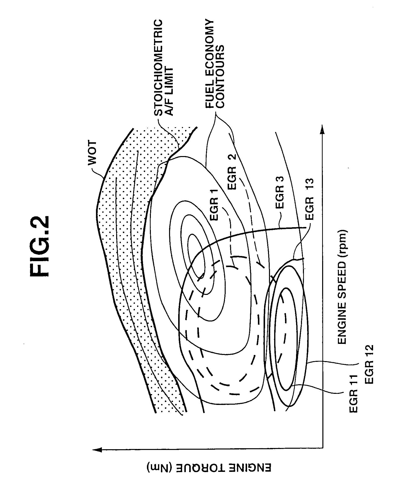
[0062] The control system of the before-mentioned patent document D2 (JP H03(1991)-172666) delays a shift operation of a continuously variable transmission having a lockup mechanism. In the case of vehicle acceleration in a lockup region, this control system releases the lockup mechanism and delays the shift operation, to improve the acceleration response.) However, during the delay of the shift operation, the transmission ratio is held fixed, and the load of the engine is increased significantly, to the disadvantage of the fuel economy especially when the acceleration is requested at a relatively high load region. To produce the vehicle driving force requested by the driver without varying the transmission ratio, the engine system must increase the engine load as compared to the engine operation with variation of the transmission. Therefore, the engine operating point readily enters the fuel economy deterioration r...


PUM


Abstract

A control apparatus for an internal combustion engine with an exhaust recirculation system includes an acceleration request sensing section to sense a driver's acceleration request; and an engine operating condition sensing section to sense a current engine operation condition at the time of detection of the driver's acceleration request, to determine a margin from the engine operating condition at the time of detection of the driver's acceleration request, to a fuel economy deterioration region on a higher load side. A controlling section controls the EGR quantity, such as EGR rate, of the exhaust recirculation system in accordance with the margin.

Description

BACKGROUND OF THE INVENTION [0001] The present invention relates to control technique for an internal combustion engine with an exhaust gas recirculation system or for an internal combustion engine combined with a continuously variable transmission. [0002] An exhaust gas recirculation (EGR) system is apparatus for recirculating part of exhaust gases discharged from an engine, to the intake side of the engine, to reduce the emission of NOx. Recently, the exhaust gas recirculation is used not only for the emission control, but also as one of techniques for improving the fuel consumption by reduction of pumping loss with a greater amount of EGR in a wider engine operation range. [0003] Patent document D1 (JP 2000-205004A) shows an engine control system arranged to decrease an exhaust gas recirculation quantity during vehicle acceleration with depression of an accelerator pedal, to improve the vehicle acceleration response. Patent document D2 (JP H03(1991)-172666) shows a control system...

Claims


Application Information

Patent Timeline
Patent Type & Authority Applications(United States)
IPC IPC(8): B60W10/06B60W10/10B60W30/18F02D21/08F02D41/00F02D41/10F02D41/14F16H61/00F16H61/66
CPCB60K2741/145B60W10/06B60W10/107B60W30/1882F02D21/08F02D41/005Y10T477/624F16H61/66F16H2061/0015Y02T10/76Y02T10/47Y10T477/62427F02D41/10B60W10/04B60W10/101B60W30/1819Y02T10/40
Inventor YOSHIOKA, YOUKOSATO, TAKESHI
Owner NISSAN MOTOR CO LTD
Why Eureka
Try Eureka