Powered adjustable pipe wrench

a technology of adjustable wrenches and adjustable spouts, which is applied in the field of tools, can solve the problems of no powered tool developed specifically for this potentially unsafe, physically strenuous, everyday process, and injury to the person performing this function

Inactive Publication Date: 2012-03-27
MYBURGH HERMAN
View PDF12 Cites 10 Cited by
  • Summary
  • Abstract
  • Description
  • Claims
  • Application Information

AI Technical Summary

Problems solved by technology

This operation often requires the exertion of significant human physical force for proper performance, and may result in injury to the person performing this function, as well as injury to helpers or bystanders.
However, the majority of the plumbing work involving the threading and unthreading of pipes and pipe fittings has to be done overhead while working in the air on a platform or the like.
Despite substantial awareness of worker safety, as well as increased legislation in this field, no powered tool has yet been developed specifically for this potentially unsafe, physically strenuous, everyday process wherein two pipe components must be rotated relative to one another.

Method used


Image

  • Powered adjustable pipe wrench
  • Powered adjustable pipe wrench
  • Powered adjustable pipe wrench

Examples


second embodiment

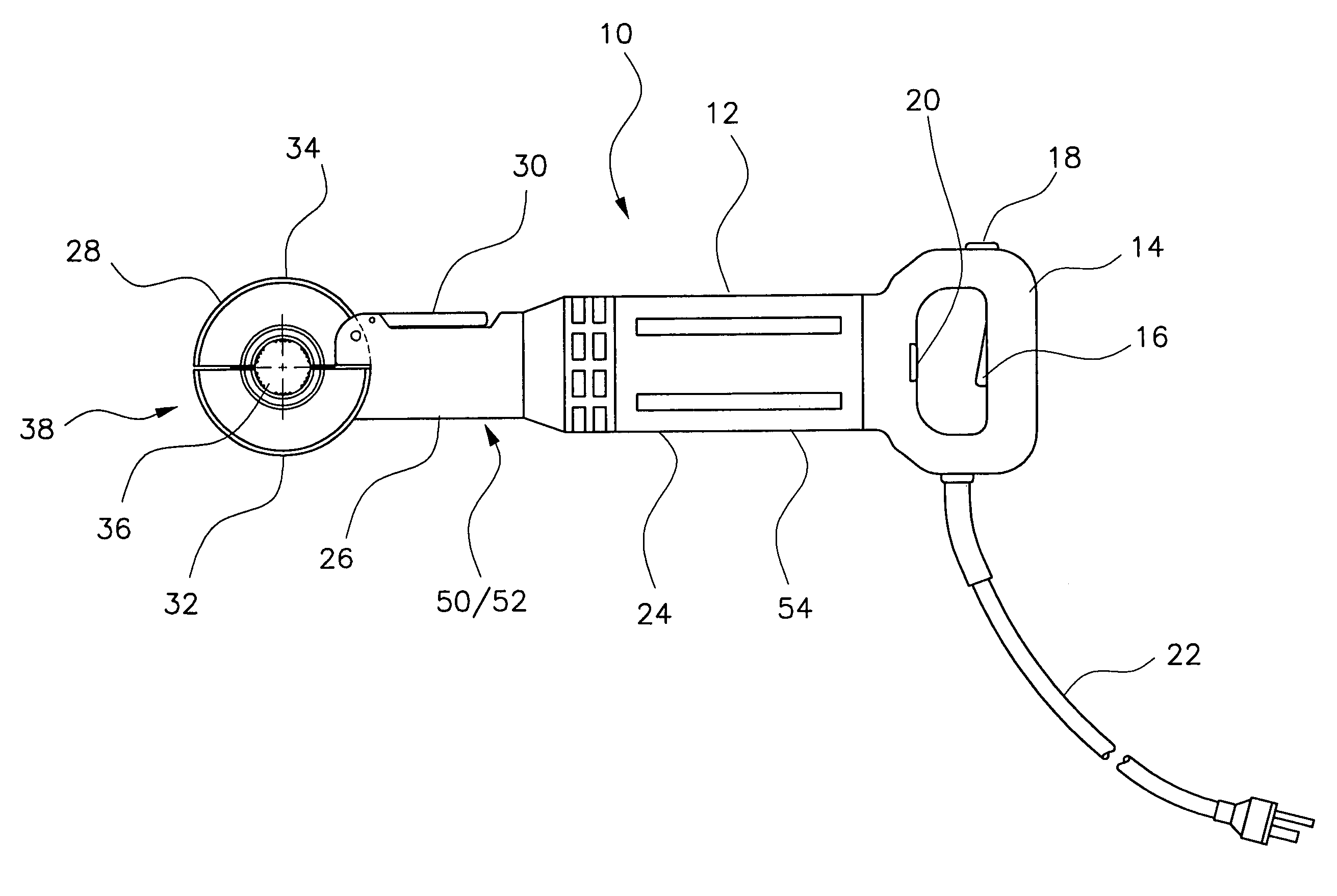
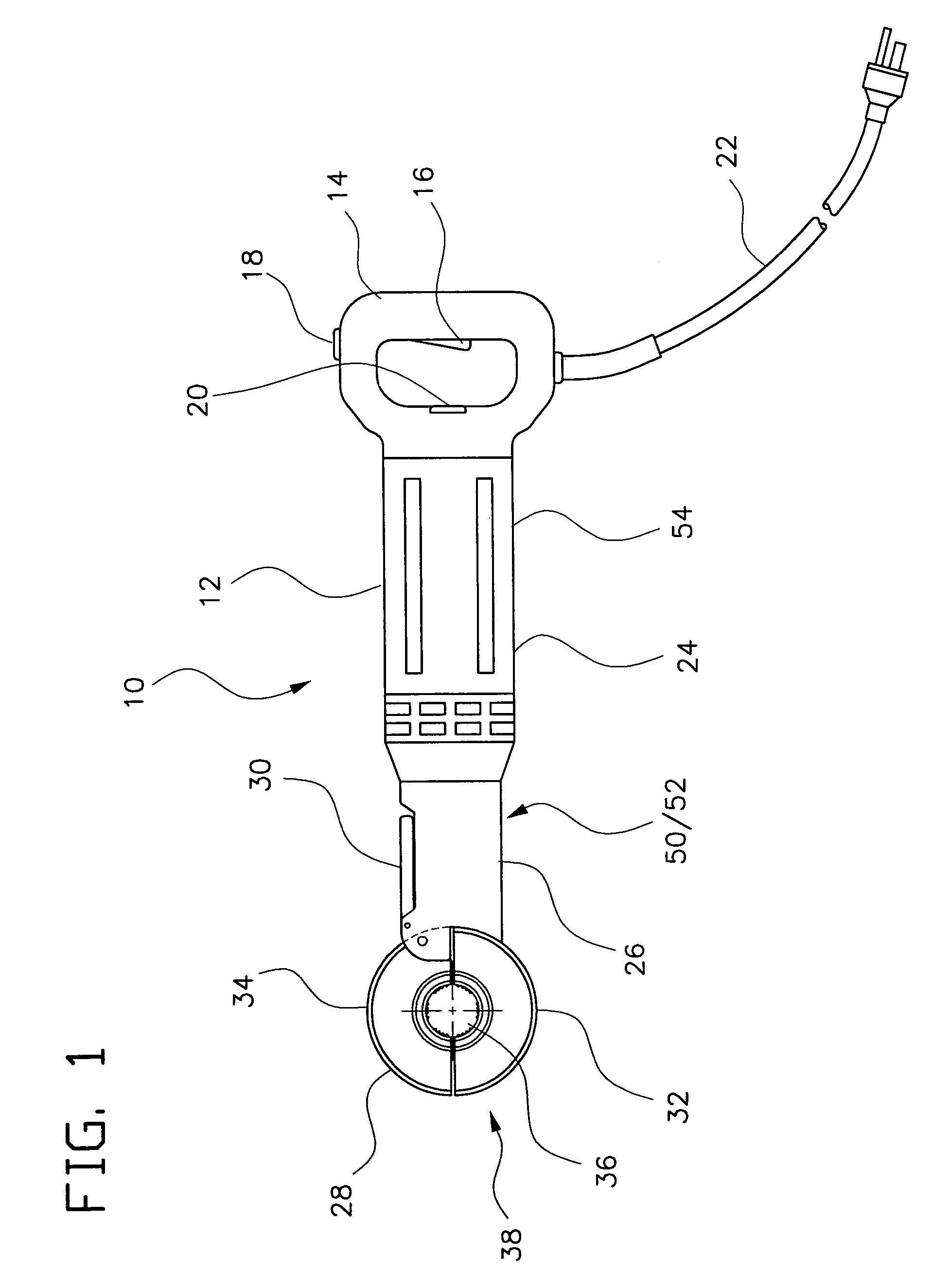
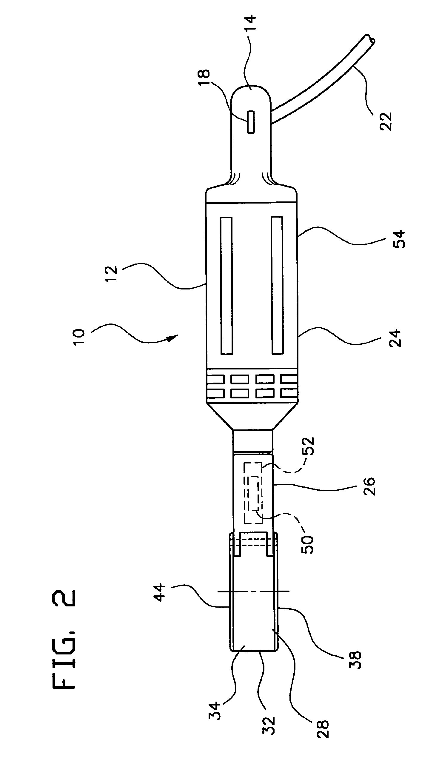
[0036]FIGS. 5 through 9 of the drawings provide illustrations of the powered adjustable pipe wrench, designated as wrench 100. The powered adjustable pipe wrench 100 includes an elongate housing 102 having a handle portion 104 extending therefrom and a first jaw portion 106 at the end opposite the handle 104. The first jaw portion 106, i.e., the jaw portion integral with the housing 102, includes a powered, rotary grip assembly disposed therein, with the rotary grip assembly having arcuately spaced, coplanar first and second powered rollers 108a and 108b (shown in FIGS. 7 and 8) therein. The two rollers 108a and 108b are mounted on respective shafts 109a and 109b, with both shafts and the second roller 108b being shown in FIG. 8, roller 108a being mounted on shaft 109a and hidden behind the gear train in FIG. 8.

[0037]A motor 110, shown in FIGS. 8 and 9, drives the powered rollers 108a and 108b through a gear train 112, which mechanically couples the motor 110 to the rollers 108a, an...

embodiment 100

[0045]FIGS. 10 and 11 provide perspective views in axial section of alternative embodiments of the powered adjustable pipe wrench, in which various configurations of the adjuster knob have been relocated relative to the wrench embodiment 100 of FIGS. 5 through 9. Identical reference numerals are used to indicate substantially identical components in the powered wrench embodiments of FIGS. 5 through 11, with only the overall wrenches and differently configured components thereof being assigned different reference numerals. The powered wrench 200 of FIG. 11 has substantially the same configuration as the wrench 200 of FIG. 10, with the exception of the differently configured adjuster knob 230b.

[0046]The powered wrench 200 of FIGS. 10 and 11 is substantially the same as the powered wrench 100 of FIGS. 5 through 9, with the exception of the relocation of the jaw adjustment knob 230a or 230b and necessary changes to the associated mechanism. Rather than placing the adjuster knob at the ...


PUM


Abstract

The powered adjustable pipe wrench has a motorized rotary grip to rotate a pipe component clamped therein and a laterally spaced stationary grip to hold a second pipe component stationary relative to the first as it is being rotated. The pipe wrench may have a cylindrical jaw housing with semicylindrical fixed and openable portions hinged to one another. One end of the housing includes a powered component to rotate the pipe component held therein, while the other housing end includes jaw components holding the second pipe component stationary. Alternatively, the pipe wrench may have a powered component extending from the jaw of the wrench body to rotate the first pipe component, and a rectilinearly adjustable jaw portion extending from the wrench body. A set of jaw components is axially spaced from the rotary component to hold the second pipe component stationary.

Description

CROSS-REFERENCE TO RELATED PATENT APPLICATIONS[0001]This application is a continuation-in-part of U.S. patent application Ser. No. 12 / 003,380 filed on Dec. 21, 2007, now U.S. Pat. No. 7,530,294 which is a continuation-in-part of U.S. patent application Ser. No. 11 / 907,516 filed on Oct. 12, 2007, now abandoned which claims the benefit of U.S. Provisional Patent Application Ser. No. 60 / 851,281 filed on Oct. 13, 2006.BACKGROUND OF THE INVENTION[0002]1. Field of the Invention[0003]The present invention relates generally to tools used in the plumbing trade, and more particularly to a powered adjustable pipe wrench for use with threaded pipe and threaded pipefittings.[0004]2. Description of the Related Art[0005]The current practice of attaching, tightening, loosening, and removing threaded pipe components to one another is a manual process, with two pipe wrenches normally being employed. One pipe wrench is adjusted and attached to grip the threaded first component, e.g., a pipe fitting, e...

Claims


Application Information

Patent Timeline
Patent Type & Authority Patents(United States)
IPC IPC(8): B25B17/00
CPCB25B21/00B25B21/002B25B23/0085
Inventor MYBURGH, HERMAN
Owner MYBURGH HERMAN
Why Eureka
Try Eureka