Joint structure

a joint structure and joint technology, applied in the direction of electrical equipment, connection, coupling device connection, etc., can solve the problems of metal fatigue, different types of attenuation of signals, and manufacturing costs

Inactive Publication Date: 2012-03-27
DVINA
View PDF5 Cites 3 Cited by
  • Summary
  • Abstract
  • Description
  • Claims
  • Application Information

AI Technical Summary

Problems solved by technology

However, the longitudinal slashes cause the signals to undergo different types of attenuation.
To ensure tight engagement between the resilient element and the metallic pipe, it is necessary to increase the precision of the resilient element and the metallic pipe during a manufacturing process thereof, thereby incurring manufacturing costs.
As a result, due to the plugging and unplugging of the r...

Method used


Image

  • Joint structure
  • Joint structure
  • Joint structure

Examples


Embodiment Construction

[0007]The examples and drawings provided in the detailed description are merely examples, which should not be used to limit the scope of the claims in any claim construction or interpretation

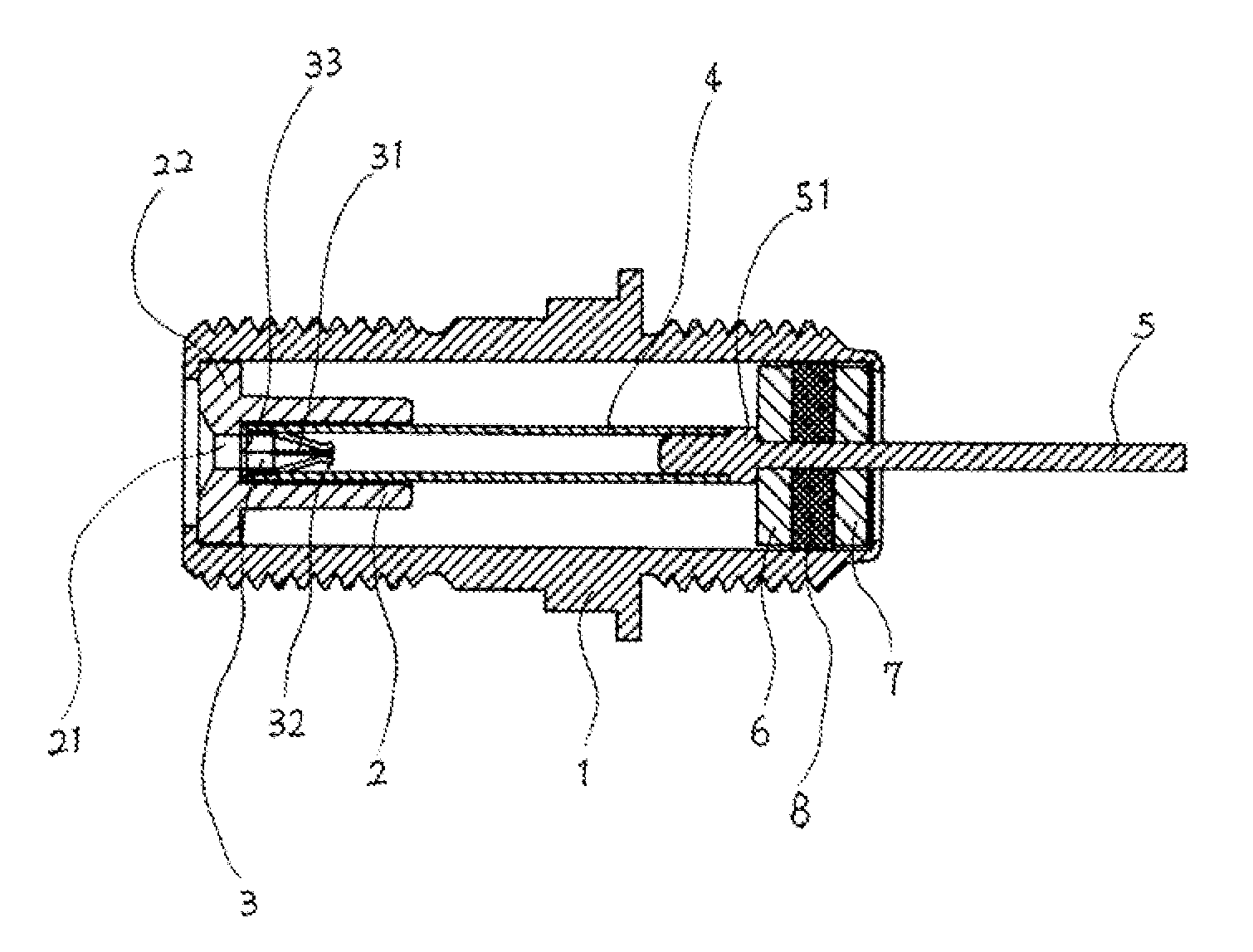
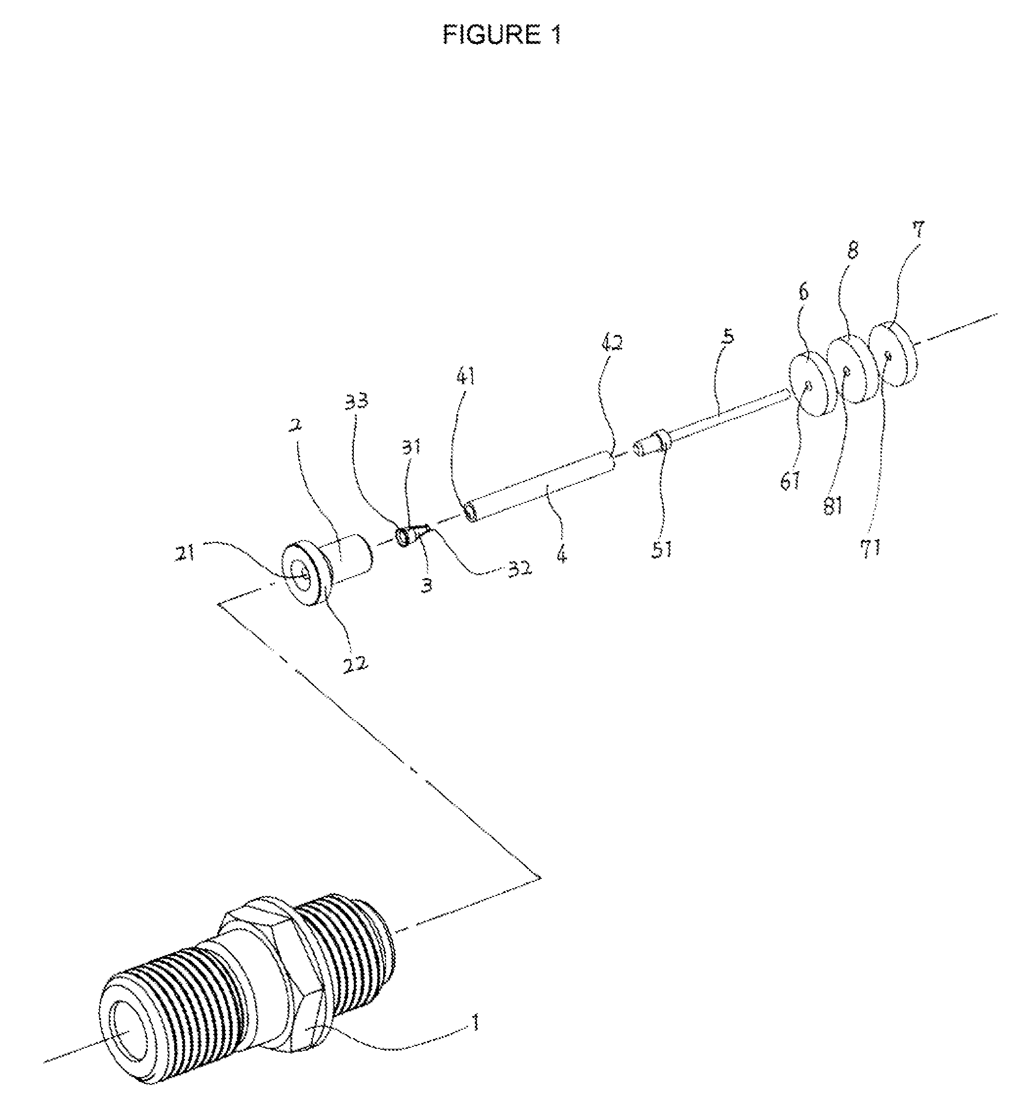
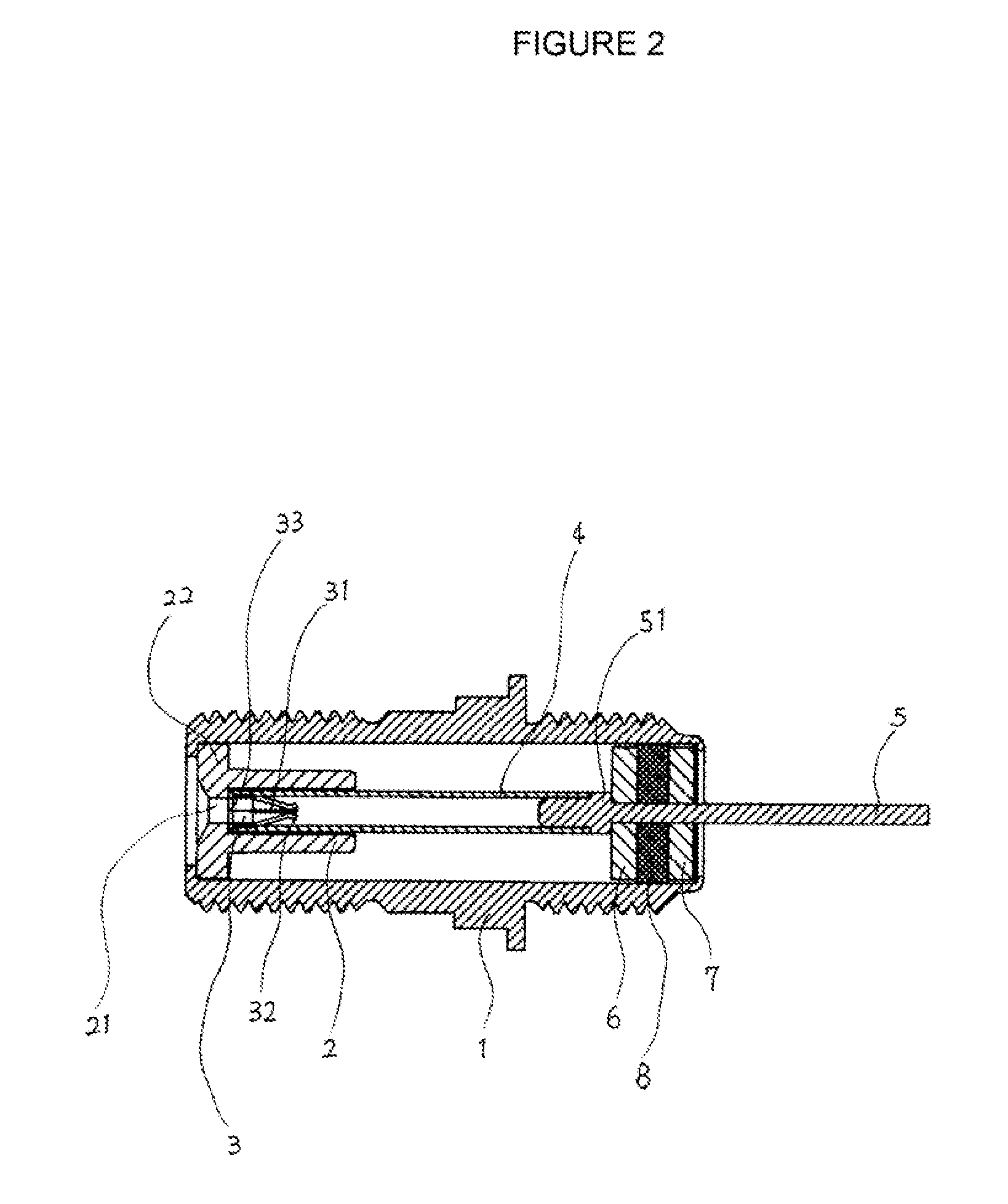
[0008]Referring to FIGS. 1, 2, the joint structure in one example, comprises a body 1 provided externally with threads and provided internally with a cylindrical hollow core for accommodating a sleeve 2 therein. The sleeve 2 has a positioning ring 22 disposed at one end of the sleeve 2 and an aperture 21 disposed at a central portion of the sleeve 2. A resilient element 3 may be received inside the sleeve 2.

[0009]Referring to FIGS. 1, 3, the circumference of the resilient element 3 is integrally formed as a unitary unit, and has a plurality of longitudinal slashes 31. A positioning ring 33 and at least one bump 32 are disposed at two ends of the resilient element 3, respectively. The resilient element 3 may be disposed in a hollow metallic pipe 4 in a manner that the joining portion of the resil...


PUM


Abstract

A joint structure effective in reducing return loss and insertion loss of signals includes a body, a sleeve, a resilient element, a metallic pipe, a rod, two washers, and a packing. The sleeve is disposed in the body and penetrable by a terminal line. The sleeve has a positioning ring circumferentially in tight contact with the body and receives the resilient element. The circumference of the resilient element is integrally formed as a unitary unit and has longitudinal slashes whose ends are provided with bumps, respectively. A positioning ring is disposed at the other end of the resilient element. The resilient element and the rod are insertable into two ends of the metallic pipe, respectively. The rod has an end for penetrating the washers and packing, and has a positioning ring for enabling engagement and positioning of the washers, the packing, the rod, and the metallic pipe.

Description

FIELD OF THE INVENTION[0001]The field relates to joint structures, and more particularly, to a joint structure comprising: a metallic pipe configured to transmit an electronic signal and enhanced with slash-free design; a resilient element completely enclosed by the metallic pipe and equipped with a positioning ring in seamless contact with the inner wall of the metallic pipe, such that the surface of the metallic pipe is free of breakages and sharp protrusions, wherein not only can the standing wave ratio and echo attenuation of a high-frequency signal being transmitted be minimized to thereby efficiently reduce the return loss and insertion loss of the signal, but the resilient element is provided with bumps for restricting expansion of the resilient element within the metallic pipe to thereby reduce the tendency of the resilient element to undergo metal fatigue, enhance the performance of the resilient element, increase the resilience of the resilient element, and boost the force...

Claims


Application Information

Patent Timeline
IPC IPC(8): H01H29/00
CPCH01R9/0521
Inventor HUANG, CHUAN-HSI
Owner DVINA
Why Eureka
Try Eureka