
Signal encoding apparatus and method, signal decoding apparatus and method, programs and recording mediums

a signal encoding and signal technology, applied in the field of signal encoding apparatus, signal encoding method, signal decoding apparatus, signal decoding method, etc., can solve the problems of not being able to achieve satisfactory sound quality and no dramatic improvement of sound quality, and achieve high-quality time series signal

Active Publication Date: 2012-03-27
SONY CORP
View PDF14 Cites 21 Cited by
  • Summary
  • Abstract
  • Description
  • Claims
  • Application Information

AI Technical Summary

Benefits of technology

This approach allows for high-quality frequency band expansion that reduces distortions and maintains sound quality by adjusting frequency amplitude peaks and gains, resulting in improved sound reproduction.

Problems solved by technology

While such techniques are advantageous in that they do not have to modify the format and make it suffice to improve the sound quality only at the decoding side, no dramatic improvement of sound quality is achieved because the band is expanded only from the received signals and distortions are noticeable to the auditory sense in a high band depending on the input sound source particularly when the low band and the high band are scarcely correlated.
While such techniques provide an effect of improving voice signals, distortions of audio signals are noticeable to the auditory sense and hence is not able to realize a satisfactory sound quality.

Method used


Image

  • Signal encoding apparatus and method, signal decoding apparatus and method, programs and recording mediums
  • Signal encoding apparatus and method, signal decoding apparatus and method, programs and recording mediums
  • Signal encoding apparatus and method, signal decoding apparatus and method, programs and recording mediums

Examples


Embodiment Construction

[0033]Now, the present invention will be described in greater detail by referring to the accompanying drawings that illustrate preferred embodiments of the invention.

[0034]Firstly, the signal encoding apparatus according to an embodiment of the present invention will be described below.

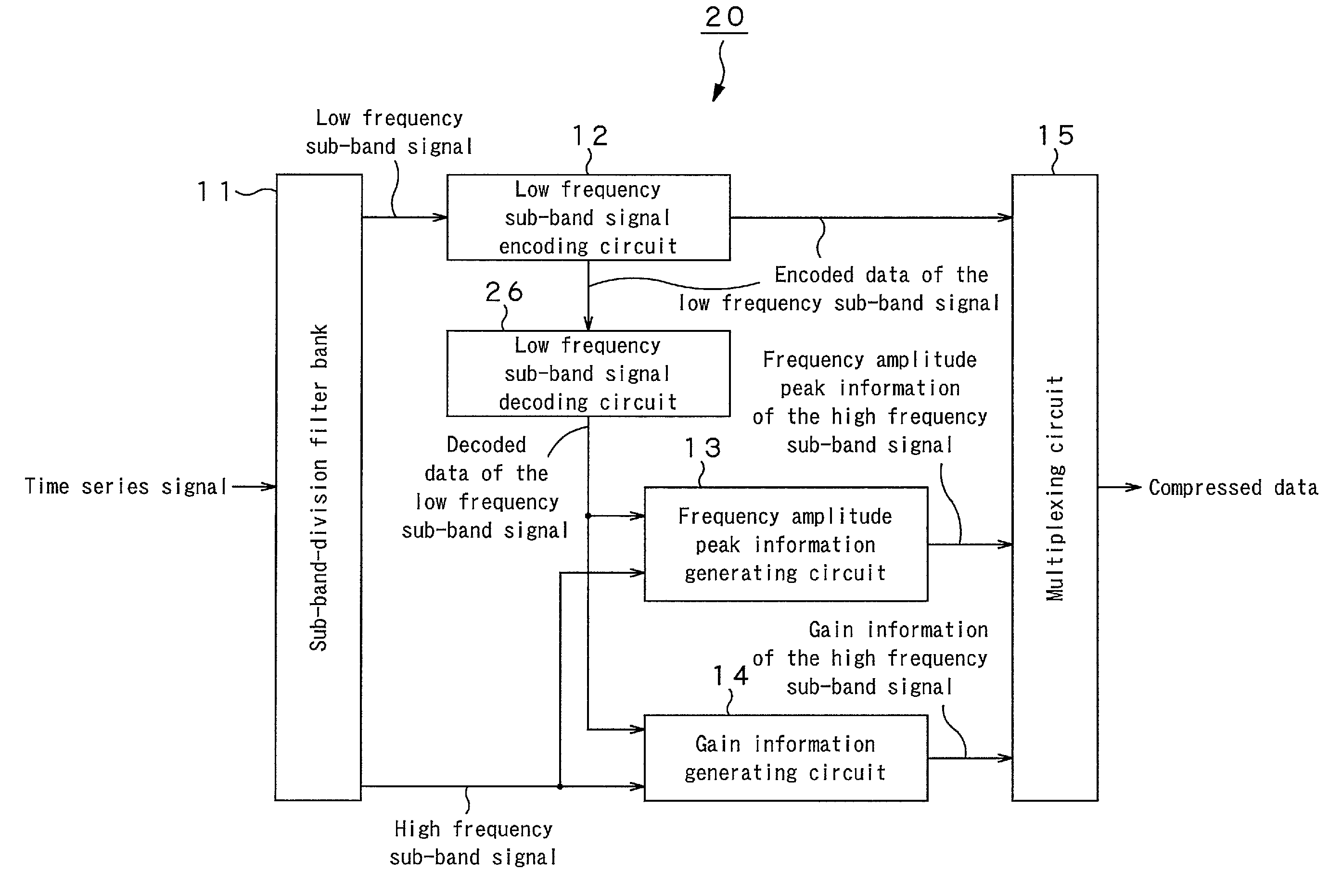
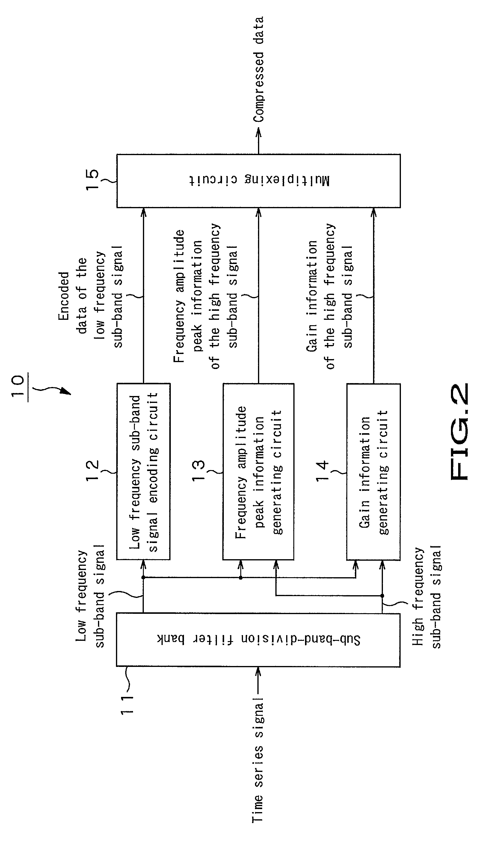
[0035]Referring to FIG. 2, the signal encoding apparatus 10 of this embodiment has a sub-band-division filter bank 11, a low frequency sub-band signal encoding circuit 12, a frequency amplitude peak information generating circuit 13, a gain information generating circuit 14 and a multiplexing circuit 15.

[0036]The sub-band-division filter bank 11 divides an input time series signal into a plurality of sub-bands and supplies a low frequency sub-band signal formed by a plurality of low frequency side sub-bands to the low frequency sub-band signal encoding circuit 12, the frequency amplitude peak information generating circuit 13 and the gain information generating circuit 14.

[0037]The sub-band-division f...


PUM


Abstract

The encoding apparatus generates information for generating a high quality high frequency sub-band signal when expanding the frequency band at the decoding apparatus. A signal encoding apparatus divides an input time series signal into a plurality of sub-bands and encodes a low frequency sub-band signal to generate encoded data of the low frequency sub-band signal. Concurrently, it compares the frequency amplitude peak of the new high frequency sub-band signal generated from the low frequency sub-band signal and the original high frequency sub-band signal and generates frequency amplitude peak information of the high frequency sub-band signal. Similarly, it compares the gain of the new high frequency sub-band signal generated by using the low frequency sub-band signal and the original high frequency sub-band signal and generates gain information of the high frequency sub-band signal. Subsequently, the signal encoding apparatus multiplexes the encoded data of the low frequency sub-band signal, the frequency amplitude peak information of the high frequency sub-band signal and the gain information of the high frequency sub-band signal and outputs compressed data.

Description

CROSS REFERENCES TO RELATED APPLICATIONS[0001]The present invention contains subject matter related to Japanese Patent Application JP 2005-202278 filed in the Japanese Patent Office on Jul. 11, 2005, the entire contents of which being incorporated herein by reference.BACKGROUND OF THE INVENTION[0002]1. Field of the Invention[0003]The present invention relates to a signal encoding apparatus, a signal encoding method, a signal decoding apparatus, a signal decoding method, programs and recording mediums that can suitably be used for expanding a sub-band signal limited to a certain frequency band at the encoding side to a broader frequency band at the decoding side.[0004]2. Description of the Related Art[0005]It has been made technically possible in recent years to compress the data of a CD (compact disc) and reduce the quantity of data to about 1 / 10 of the original quantity by utilizing the mechanism of the auditory sense of human being for the purpose of highly efficiently encoding au...

Claims


Application Information

Patent Timeline
Patent Type & Authority Patents(United States)
IPC IPC(8): H04L27/00G10L19/02G10L21/0388
CPCH04L27/00G10L19/0204
Inventor CHINEN, TORUHONMA, HIROYUKI
Owner SONY CORP
Learn More