Apparatus and method for installing anchor bolts in a cylindrical pier foundation

a technology of cylindrical piers and anchor bolts, which is applied in the field of concrete foundations, can solve the problems of large number of personnel, large assembly, and potential safety hazards, and achieve the effects of reducing the risk of accidents, reducing the safety of workers, and increasing the cost of construction

Inactive Publication Date: 2012-04-03
TOOMAN NORMAN L
View PDF16 Cites 8 Cited by
  • Summary
  • Abstract
  • Description
  • Claims
  • Application Information

AI Technical Summary

Benefits of technology

[0012]The number of bolts in each bolt package will generally be about ten to twelve bolts. Of course this number may vary according to various design and installation factors, without changing the basic concept of the embodiments of the method and apparatus disclosed herein. The installation of the above-described bolt packages eliminates the need for a large number of personnel inside the bore hole lifting each individual bolt so that the upwardly facing end of each bolt may be attached to a template. It further eliminates the need to lift the entirety of the bolts with the template as depicted in FIG. 3 so that the downwardly facing ends may be set within the anchor plates, because the anchor plates have already been installed in sections to each bolt package. The utilization of the position retention means for each bolt package eliminates the need for the placement of bands or rebar around the collective bolts to hold the bolts in position during the pouring of the concrete, because the position retention means accomplishes this purpose. As yet another benefit, the known method requires that each bolt be attached to the template with a nut in order for the bolt to be suspended by the template. Because the present method does not require the template to support the collective weight of all of the anchor bolts, a much lighter template may be utilized for the formation of the grout trough and not every bolt needs to have a nut attached to the template at the upwardly facing end of the bolt.

Problems solved by technology

After all of the bolts are hung from the template, the entire assembly, including the lifting frame, is very heavy, requiring the use of a crane having a lifting capacity of approximately 100 tons.
For example, it requires a large number of workers working below a very heavy assembly, creating a potential safety hazard.
It also requires a large number of personnel in the borehole to expeditiously hang the bolts from the template.

Method used


Image

  • Apparatus and method for installing anchor bolts in a cylindrical pier foundation
  • Apparatus and method for installing anchor bolts in a cylindrical pier foundation
  • Apparatus and method for installing anchor bolts in a cylindrical pier foundation

Examples


Embodiment Construction

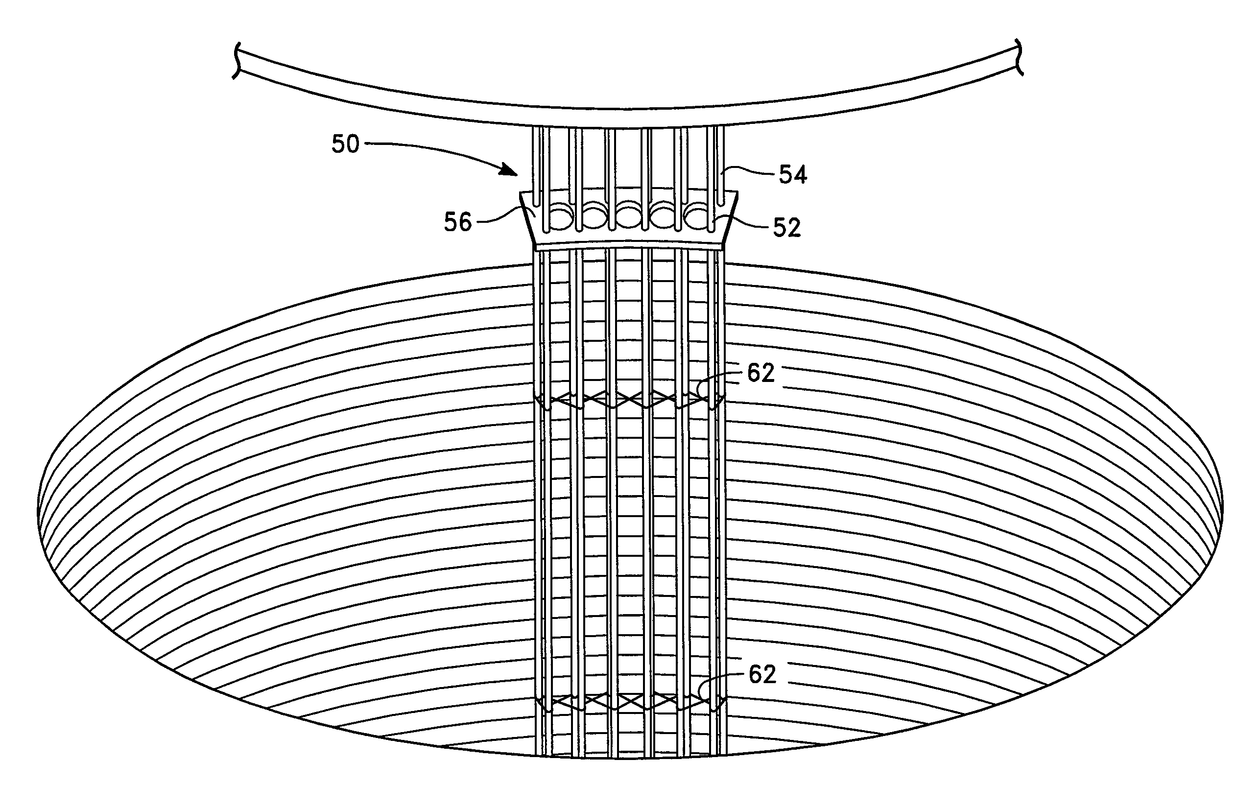
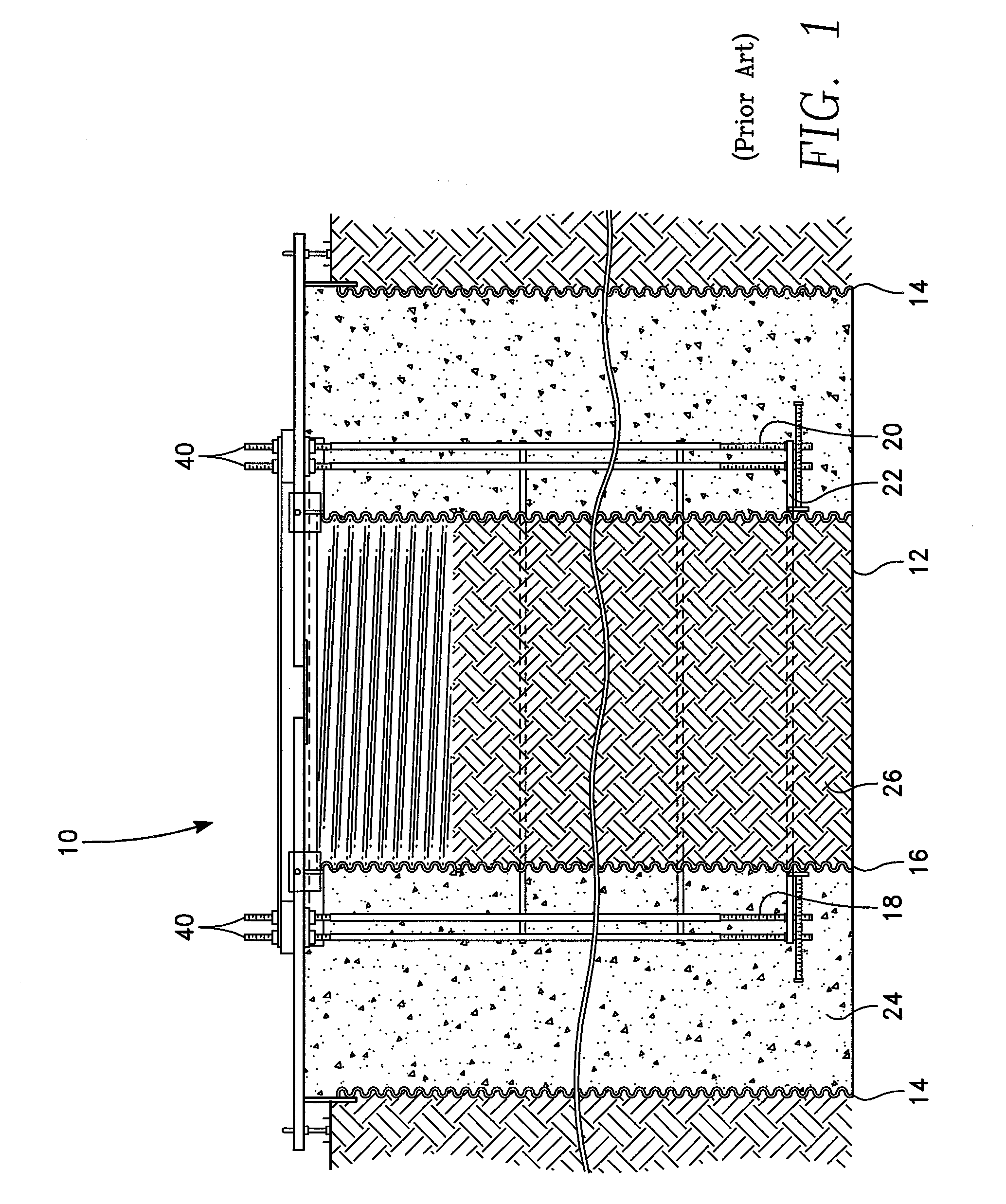
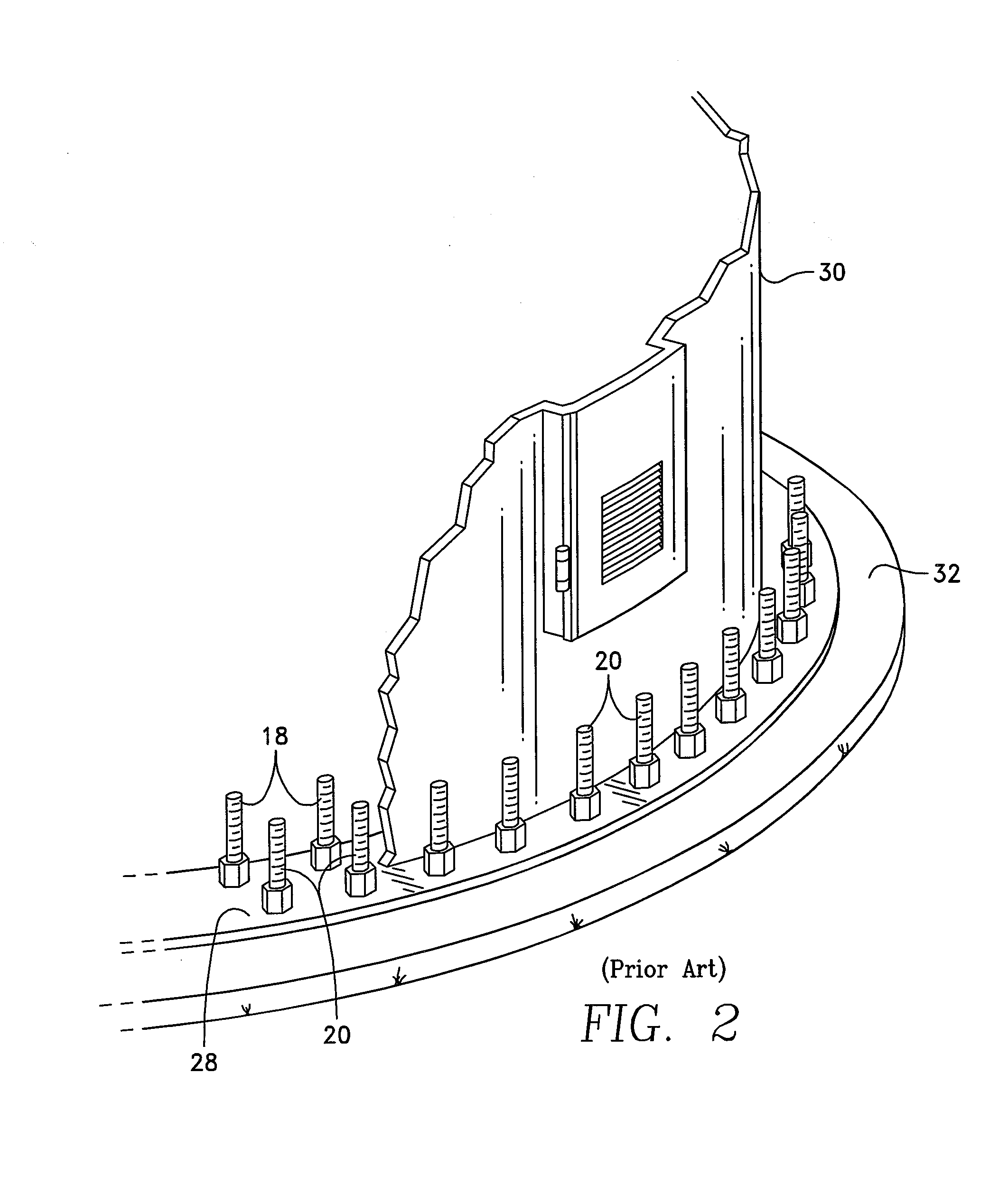
[0034]Referring specifically to the figures, FIG. 1 depicts an embodiment of a known foundation 10 utilized for installation of a relatively tall vertical structure, such as a wind turbine. It is to be appreciated that while the disclosed method and apparatus may be utilized to obtain a foundation 10 such as that depicted in FIG. 1, the procedure for obtaining the foundation is entirely different from the known methods. Foundation 10 comprises a bore hole 12, an outer boundary shell 14 and an inner boundary shell 16, each typically fashioned of corrugated metal pipe (“CMP”), set within the bore hole hole. An inner ring 18 of bolts 40 and an outer ring 20 of bolts 40 are disposed within the annulus formed between the outer boundary shell 14 and the inner boundary shell 16, with the bolts 40 anchored at the lower end of the bore hole 12 to an inbed plate 22. The annulus between the outer boundary shell 14 and the inner boundary shell 16 is filled with concrete 24 and the portion of th...


PUM


Abstract

In a foundation for a wind turbine, the foundation has a large number of anchor bolts which are axially placed within the bore hole for mounting a tower flange of the wind turbine. In contrast to the practiced method, the present invention utilizes the fabrication of separate bolt packages, in which the bolts of each bolt package are configured to have an inner arc of bolts and outer arc of bolts, where each bolt in the bolt package is retained, by position retention means, in a fixed position with respect to the position of the other anchor bolts in the pre-assembled package. The present invention describes the position retention means for forming each pre-assembled package and a method of using the position retentions for constructing a foundation for a wind turbine.

Description

CROSS-REFERENCE TO RELATED APPLICATIONS[0001]U.S. Provisional Application No. 61 / 333,231 for this invention was filed on May 10, 2010, for which application this inventor claims domestic priority.BACKGROUND OF THE INVENTION[0002]This invention relates to concrete foundations set within excavations or bore holes which are installed to support wind turbines. More particularly, this invention comprises an apparatus and method for configuring, installing, and setting the anchor bolts for a cylindrical foundation for a wind turbine prior to pouring the concrete.[0003]U.S. Pat. Nos. 5,586,417 and 5,826,387, both by Henderson, disclose a foundation “which can be poured-on-site monolithically and is of cylindrical construction with many post-tensioned anchor bolts which maintain the poured portion of the foundation under heavy compression, even during periods when the foundation may be subject to high overturning moment.” Henderson's foundation is preferably in the shape of a cylinder, havi...

Claims


Application Information

Patent Timeline
Patent Type & Authority Patents(United States)
IPC IPC(8): E02D27/00
CPCE02D27/42
Inventor TOOMAN, NORMAN L.
Owner TOOMAN NORMAN L
Why Eureka
Try Eureka