Vehicle door lock device

a technology for vehicle doors and locks, applied in passenger locks, door actuation, lock applications, etc., can solve the problems of increased number of switches, operation failures in each state, and complicated electrical structures, so as to improve the reliability of the device and simplify the electrical structur

Inactive Publication Date: 2012-04-03
AISIN SEIKI KK
View PDF22 Cites 23 Cited by
  • Summary
  • Abstract
  • Description
  • Claims
  • Application Information

AI Technical Summary

Benefits of technology

[0005]It is an object of the present invention to provide a vehicle door lock device that simplifies the electrical structure and improves the reliability of the device in its entirety.
[0008]In the above structures, when the locking lever is located at the unlock position, the first and second engagement pieces are engaged so that movement of the switching lever caused by the driving force of the electrical drive unit is mechanically restricted. This allows for arrangement of the movable body at the set position. When the locking lever is located at the lock position, the first and second engagement pieces are disengaged so as to allow the driving force of the electrical drive unit to move the switching lever. Thus, the movable body is moved to and arranged at the double lock position. In this manner, the movable body may be selectively moved to and arranged at the set position and the double lock position with the driving force of the single electrical drive unit in accordance with the engagement and disengagement of the switching lever corresponding to the unlock position and the lock position of the locking lever. This eliminates the need for a sensor or the like for detecting, for example, that the movable body is located at the set position (or a corresponding state of the switching lever) and allows the electrical structure to be simplified. Further, when arranging the movable body at the set position, to mechanically stop the movement of the switching lever, positional variations of the movable body are reduced in comparison to, for example, when detecting that the movable body is located at the set position using a sensor or the like. This improves the reliability of the entire device.
[0010]In this structure, when the locking lever is moved to the lock position in a state in which the movable body is located at the set position, the input of an operation force from the inside of the vehicle moves the inside lever and pushes the release lever with the pushing piece of the middle lever, which moves integrally with the inside lever. This allows for the locking lever to be moved to the unlock position.
[0012]In this structure, when the movable body is located at the unset position and the locking lever is located at the lock position, the release lever is pushed by the pushing piece of the middle lever, which moves integrally with the inside lever, and functions to move at least the locking lever to the unlock position (the so-called two-motion or one motion-function). This allows for the number of components to be reduced in comparison to when using, for example, a discrete exclusive member (lever or the like) having such a function.

Problems solved by technology

Thus, the necessary number of switches increases, and the electrical structure becomes complicated.
The may produce operation failures in each state.

Method used


Image

  • Vehicle door lock device
  • Vehicle door lock device
  • Vehicle door lock device

Examples


Embodiment Construction

[0028]One embodiment of the present invention will now be discussed with reference to the drawings.

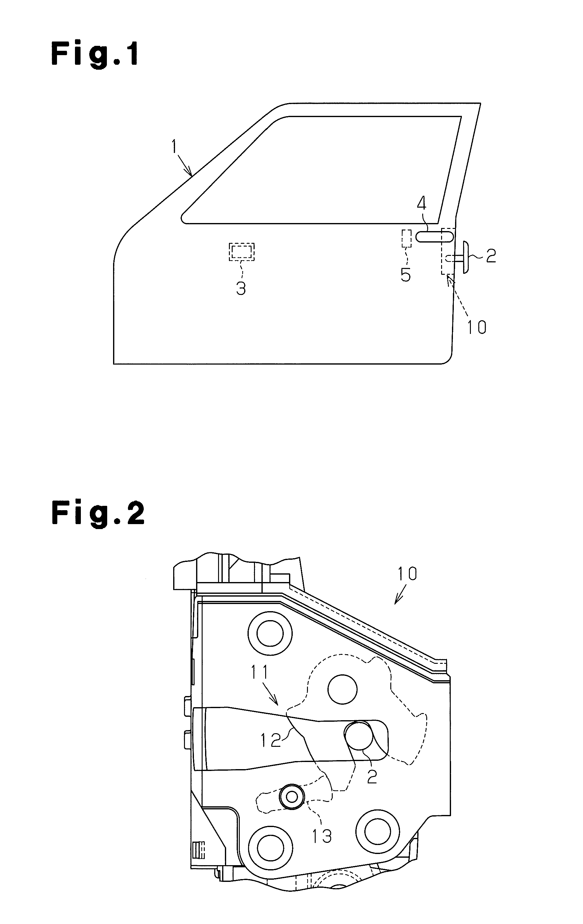
[0029]Referring to FIG. 1, a vehicle door 1 includes a door lock device 10, which is arranged along the rear rim of the vehicle door 1. The door lock device 10 is engaged with a striker 2, which is fixed to a vehicle body (not shown), to hold the vehicle door 1 in a closed state with respect to the vehicle body. Further, an inside handle 3 is arranged on an inner wall of the vehicle door 1 in a state exposed in the passenger compartment. An outside handle 4 is arranged on an outer wall of the vehicle door 1 in a state exposed to the outside of the vehicle compartment. Further, a lock knob 5, which is used for locking, is arranged on the inner wall of the vehicle door 1. To prevent theft, the lock knob 5 of the present embodiment is designed to be held within the vehicle door 1 in a locked state so as to prohibit direct operation.

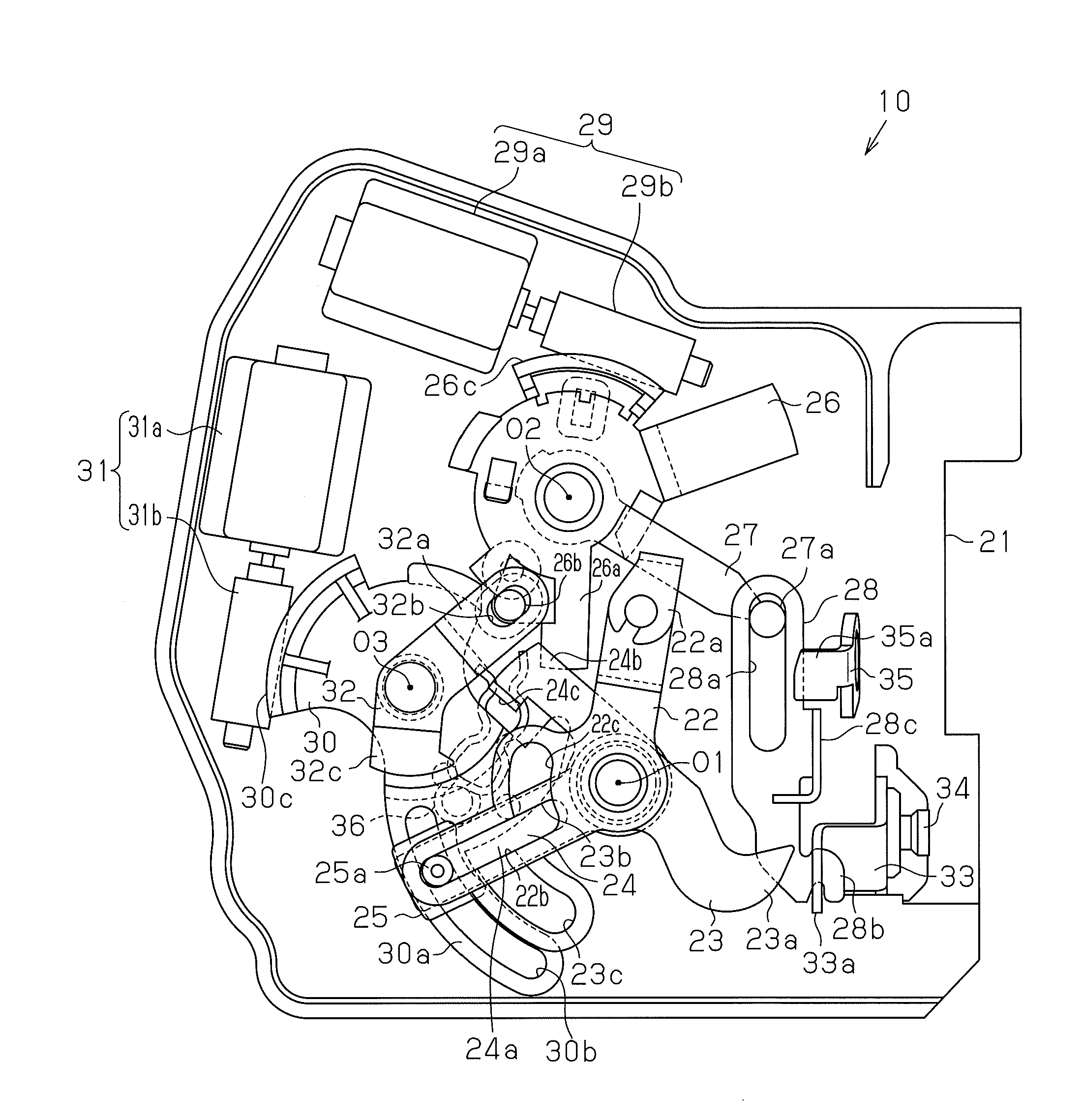
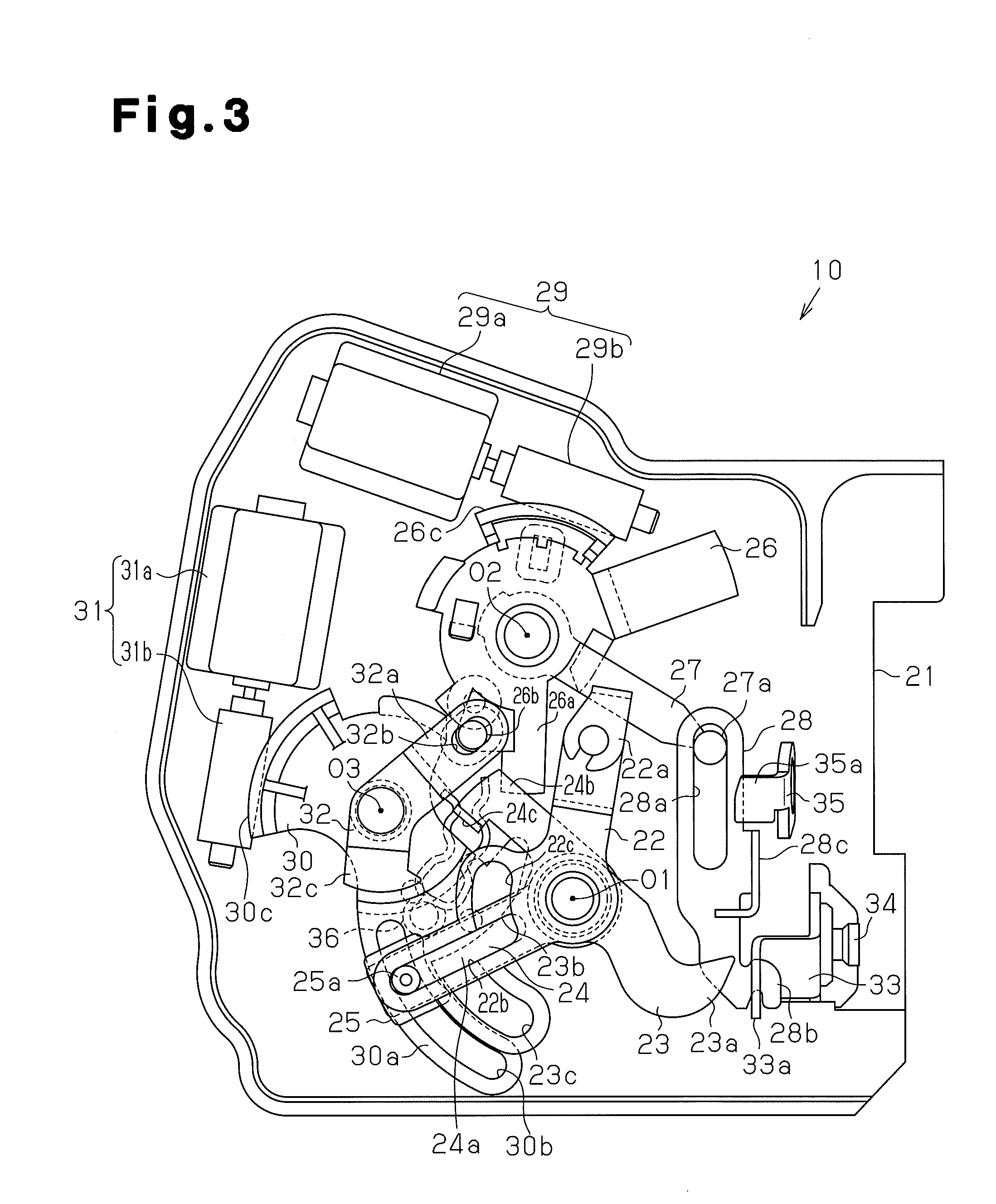
[0030]As shown in FIG. 2, the door lock device 10 include...


PUM


Abstract

A vehicle door lock device includes an active lever freely switchable between an unlock position and a lock position, a switching actuator, and a switching lever receiving drive force of the switching actuator to move a bushing. The active lever includes a first engagement piece and a second engagement piece. When the active lever is located at the unlock position, the second engagement piece engages with the first engagement piece located at a set position of the bushing to limit movement of the switching lever so that movement of the bushing is restricted within a range between an unset position and the set position. When the active lever is located at the lock position, the first engagement piece is arranged at a position avoiding engagement with the second engagement piece to allow the switching lever to move the bushing between the unset position and a double lock position.

Description

FIELD OF THE INVENTION[0001]The present invention relates to a vehicle door lock device.BACKGROUND OF THE INVENTION[0002]Patent document 1 describes an example of a vehicle door lock device known in the prior art. The door lock device includes an actuator that pivots an output lever from a neutral position in a lock direction and an unlock direction and pivots the output lever back to the neutral position with a motor, which is capable of producing forward and reverse rotation, by means of a reduction gear mechanism. When the output lever moves in the lock direction and the unlock direction, a lock-unlock lever moves to a lock position for locking a door and an unlock position for unlocking the door. The door lock device further includes a lock-unlock operation switch, a childproof operation switch, an outside handle operation detection switch, a lock actuation detection switch, an unlock actuation detection switch, a neutral detection switch, and a control unit. The outside handle ...

Claims


Application Information

Patent Timeline
Patent Type & Authority Patents(United States)
IPC IPC(8): E05C3/06E05C3/16B60J5/00B60J5/04B60R21/00E05B77/28E05B79/08E05B83/36
CPCE05B81/06E05B77/28E05B81/36E05B77/26E05B81/16E05B81/90Y10S292/23Y10T292/1082Y10T292/18Y10T292/102Y10T292/09Y10T292/108Y10T292/1047
Inventor AKIZUKI, RYUJIRONISHIO, TAKASHIYAMADA, YUSUKE
Owner AISIN SEIKI KK
Why Eureka
Try Eureka