Universal power supply system

a power supply system and universal technology, applied in the direction of substation/switching arrangement casings, contact mechanisms, coupling device connections, etc., can solve the problems of less than the optimal use of the power strip, damage to the electronic device intended to be powered, and exhausting the available electrical outlets, so as to reduce overall manufacturing costs, improve power consumption efficiency, and reduce fire hazards

Inactive Publication Date: 2012-04-03
KEEBLER JOHN C +1
View PDF41 Cites 32 Cited by
  • Summary
  • Abstract
  • Description
  • Claims
  • Application Information

AI Technical Summary

Benefits of technology

[0009]Various exemplary embodiments of a universal power supply system allows for improved power consumpti

Problems solved by technology

In some instances, not only are the output voltages and plugs different, but the polarity of the output voltage is reversed such that using a “wall wart” of the proper voltage but improper polarity could damage the electronic device intended to be powered.
Accordingly, a typical home office desk situated near a wall has only one or two available electrical outlets within reach to power such items as a desk lamp, computer, monitor, printer, telephone, speakers, network router, cable or DSL modem, etc., thus quickly

Method used


Image

  • Universal power supply system
  • Universal power supply system
  • Universal power supply system

Examples


Embodiment Construction

[0014]Various exemplary embodiments of a universal power supply system are disclosed herein. In the following detailed description, numerous specific details are set forth in order to provide a thorough understanding of the present inventive embodiments. It will be apparent, however, to one skilled in the art that the present inventive embodiments may be practiced without these specific details. In other instances, well-known structures, devices or components may be shown in block diagram form in order to avoid unnecessarily obscuring the present inventive embodiments.

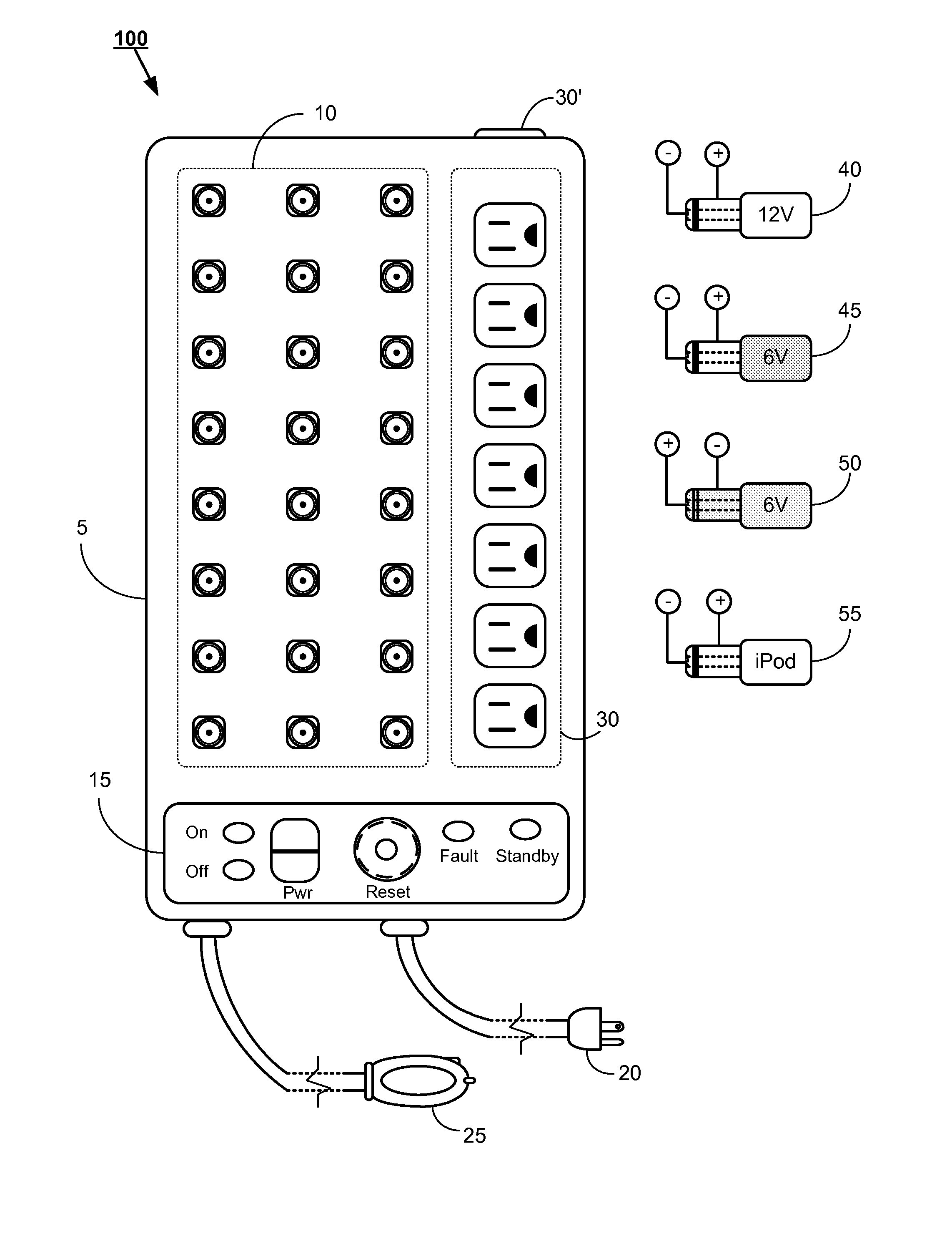
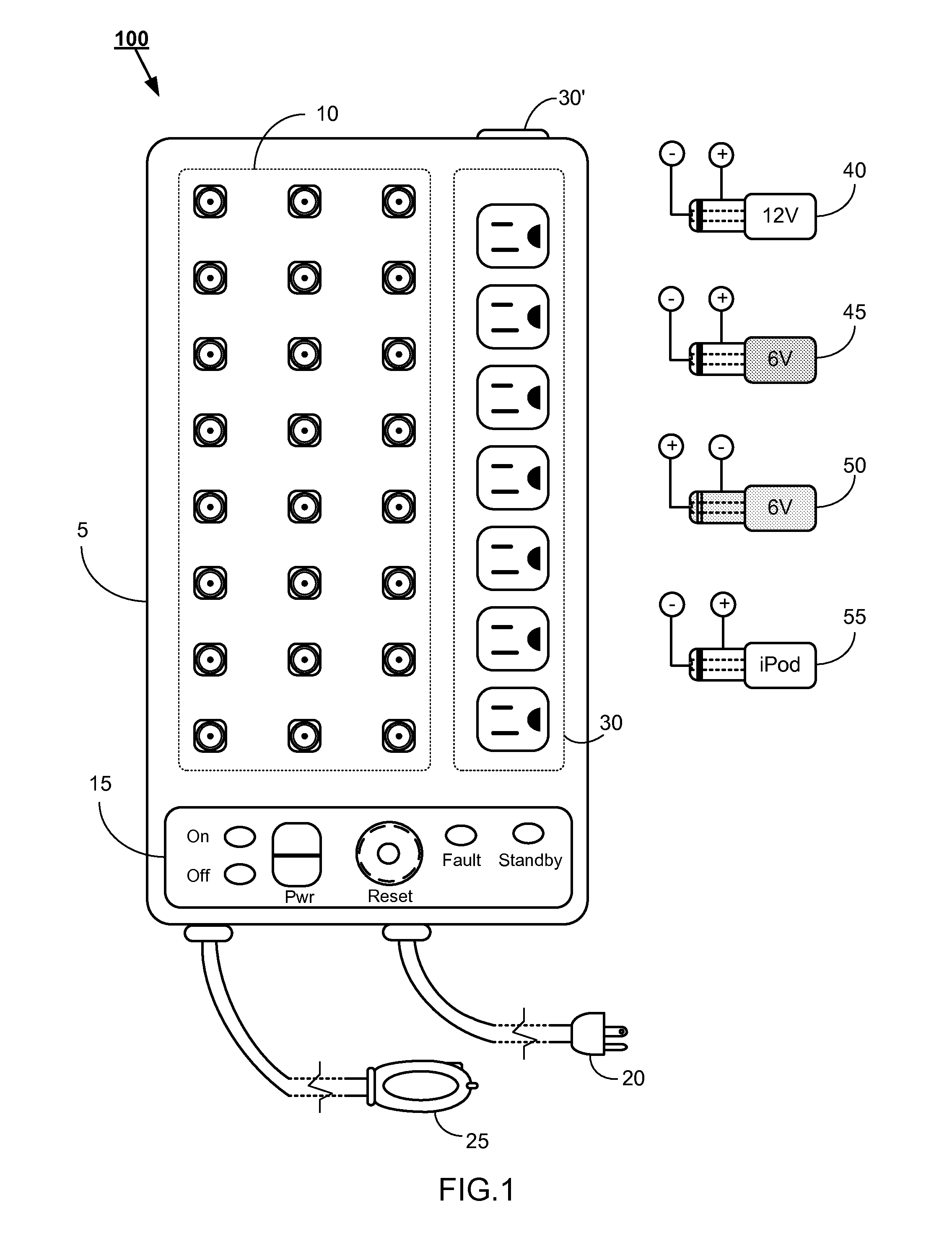
[0015]Referring to FIG. 1, a top view of a universal power supply system 100 in accordance with an exemplary embodiment is depicted. In an exemplary embodiment, the universal power supply system 100 includes a housing 5 dimensioned to encompass the electrical components and circuits which form the universal power supply system 100. The housing 5 may be constructed of any suitable materials, for example, aluminum alloys...


PUM


Abstract

A universal power supply system having a power supply configured to generate a predetermined direct current output sufficient to simultaneously power a plurality of direct current powered devices connected thereto. A plurality of identical sockets are electrically coupled in parallel with the direct current output of the power supply. Individual power cables having a standardized first plug which fits into the sockets at one end and a device specific second plug at an opposing end. A voltage regulating circuit is operatively disposed in either the standardized first plug or device specific second plug which converts the intermediate direct current voltage generated by the power supply to a direct current voltage required by a particular direct current powered device.

Description

CROSS-REFERENCE TO RELATED APPLICATIONS[0001]Not applicableRELEVENT FIELD[0002]This application is directed generally toward a power supply and more specifically toward a multiport direct current power supply.BACKGROUND[0003]Small electronic devices have become a major part of our lives. For example cellular telephones, laptop computers, network routers, computer peripherals, scanners, printers, cordless telephones, etc., generally all rely on low voltage direct current. These devices are usually connected to an alternating current outlet and converted to their proper direct current voltage utilizing a small power supply, commonly referred to as a “wall wart”. Due to lack of standardization, physical design requirements and varying electrical power requirements of the electronic devices, the “wall warts” are manufactured to specifically power each individual electronic device. In addition, each “wall wart” is fitted with a plug dimensioned to fit a particular electronic device and s...

Claims


Application Information

Patent Timeline
IPC IPC(8): H02B1/26H02H3/22
CPCH02J7/0055H02J2310/22H02J1/102H02J1/08H02J2207/40
Inventor KEEBLER, JOHN C.KEEBLER, C. STEPHEN
Owner KEEBLER JOHN C
Why Eureka
Try Eureka