Sound signal processing device, sound signal processing method, sound signal processing program, storage medium, and display device

a sound signal processing and sound signal technology, applied in signal processing, transducer details, electrical transducers, etc., can solve the problems of sound output from the speaker sound finally output from the speaker is likely to be distorted, and the base is likely to be insufficient, so as to prevent clipping in the receiving end

Inactive Publication Date: 2012-04-03
SHARP KK
View PDF31 Cites 28 Cited by
  • Summary
  • Abstract
  • Description
  • Claims
  • Application Information

AI Technical Summary

Benefits of technology

[0012]In view of the foregoing problems, the present invention was made, and an object of the present invention is to realize a sound signal processing device which prevents clipping in a receiving end device without fail and which can output a sound signal having sufficient bass sound.
[0015]Moreover, according to the arrangement, the gain of the low frequency signal amplification / attenuation means is controlled on the basis of the output signal obtained by synthesizing the amplified or attenuated low frequency signal with at least part of the sound signal. Thus, in case of outputting the resultant output signal to the receiving end device, it is possible to prevent clipping in the receiving end device without fail.
[0016]Further, according to the arrangement, the gain controlled by the gain control means is a gain of the low frequency signal amplification / attenuation means for amplifying or attenuating the separated low frequency signal. Thus, an amplification factor or an attenuation factor of the low frequency signal may increase or decrease, but an amplification factor or an attenuation factor of a middle or high frequency signal other than the low frequency signal neither increases nor decreases. Thus, even in case where the sound signal contains a low frequency signal having a great amplitude, the amplification factor of the middle or high frequency signal is kept constant. Thus, if the speaker is driven in accordance with the resultant output signal, there is no unstable sound volume at a middle or high frequency.
[0021]In case where the gain of the low frequency signal amplification / attenuation means can have a negative value, it is possible to more surely prevent occurrence of clipping in the receiving end device when a sound signal having a great amplitude exceeding a clipping level of the receiving end device is inputted to the sound signal processing device. Note that, as a state in which the sound signal having such a great amplitude can be inputted to the sound signal processing device, the following cases are conceivable. For example, in case where a virtual surround process or an equalization process is carried out at a stage preceding to the sound signal processing device to excessively emphasize a low frequency component, or in case where a multi-channel down-mix process is carried out at a stage preceding to the sound signal processing device to add plural-channel sound signals, the sound signal having a great amplitude can be inputted to the sound signal processing device.
[0024]According to the arrangement, as in the aforementioned sound signal processing device, it is possible to obtain an output signal having sufficient bass in being outputted from the speaker without any clipping in the receiving end device and without unstable sound volume at middle and high frequency bands in being outputted from the speaker.

Problems solved by technology

In case of reproducing sound with a small speaker, it is impossible to obtain a sufficient sound pressure level corresponding to bass whose frequency is equal to or lower than 100 Hz, so that generally the bass is likely to be insufficient.
However, in each of the foregoing conventional devices, an output level of the output signal exceeds an acceptable level (clip level) of a receiving end device (a D / A converter, a power amplifier, and the like), which results in such a problem that sound finally outputted from the speaker is distorted.
As a result, sound outputted from the speaker is likely to be distorted.
Further, if the gain of the amplifier is set to be low so as not to cause the clipping, the low frequency signal group is not sufficiently amplified, which results in such a problem that sufficient bass cannot be obtained.

Method used


Image

  • Sound signal processing device, sound signal processing method, sound signal processing program, storage medium, and display device
  • Sound signal processing device, sound signal processing method, sound signal processing program, storage medium, and display device
  • Sound signal processing device, sound signal processing method, sound signal processing program, storage medium, and display device

Examples


embodiment 1

[0057]The following description will explain a sound signal processing device 100 according to an embodiment of the present invention with reference to the attached drawings.

[0058]First, with reference to FIG. 1, the arrangement of the sound signal processing device 100 is described as follows.

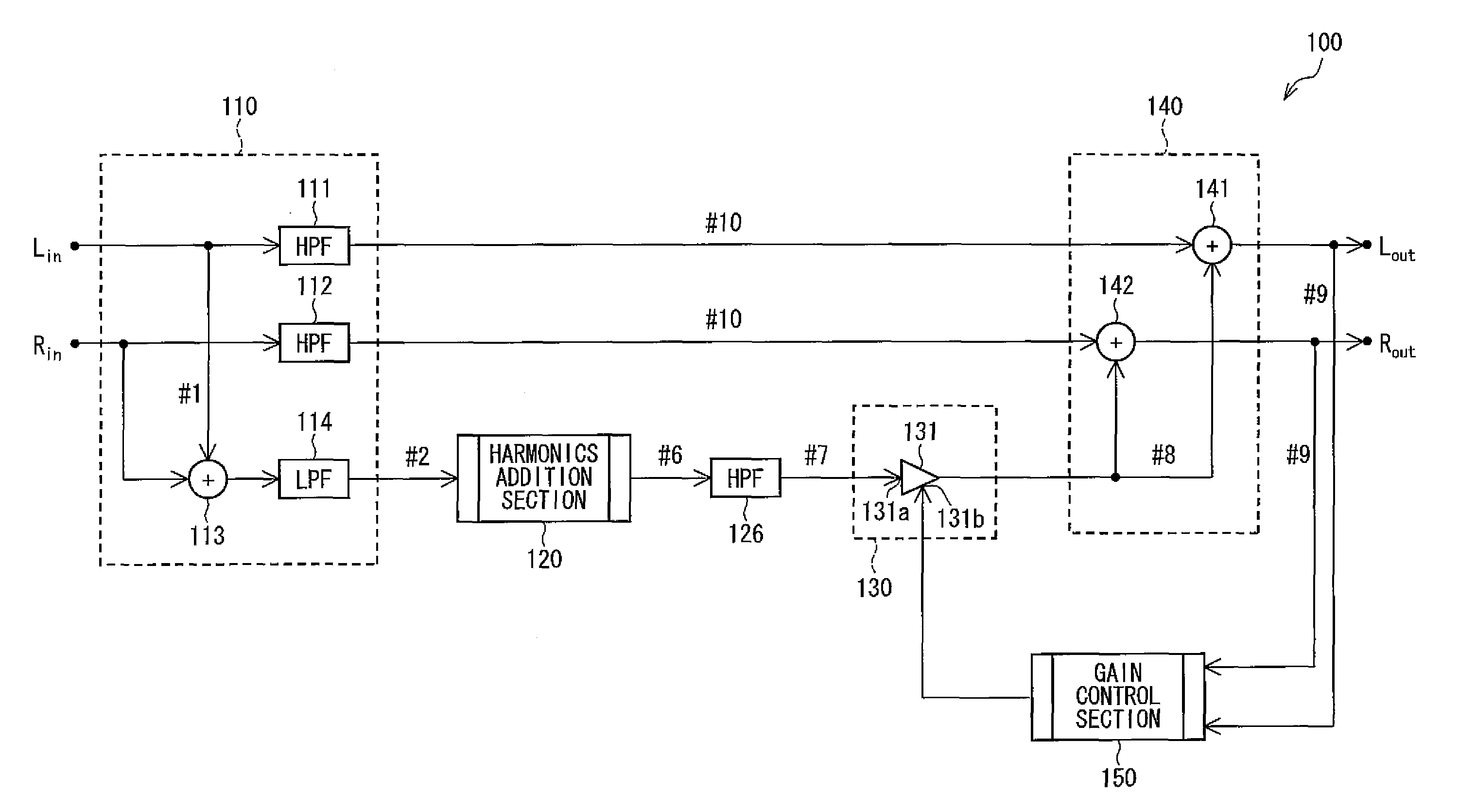
[0059]FIG. 1 is a block diagram illustrating the arrangement of the sound signal processing device 100. The sound signal processing device 100 processes digital sound signals, having been inputted via input sections Lin and Rin respectively, so as to output the processed digital sound signals via output sections Lout and Rout. As a receiving end device connected to the output sections Lout and Rout so as to receive the processed digital sound signals, a power amplifier (not shown) connected to the sound signal processing device 100 via a D / A converter (not shown) is conceivable for example.

[0060]As illustrated in FIG. 1, the sound signal processing device 100 schematically includes a sound sig...

example 1

(Example 1 of the Harmonics Addition)

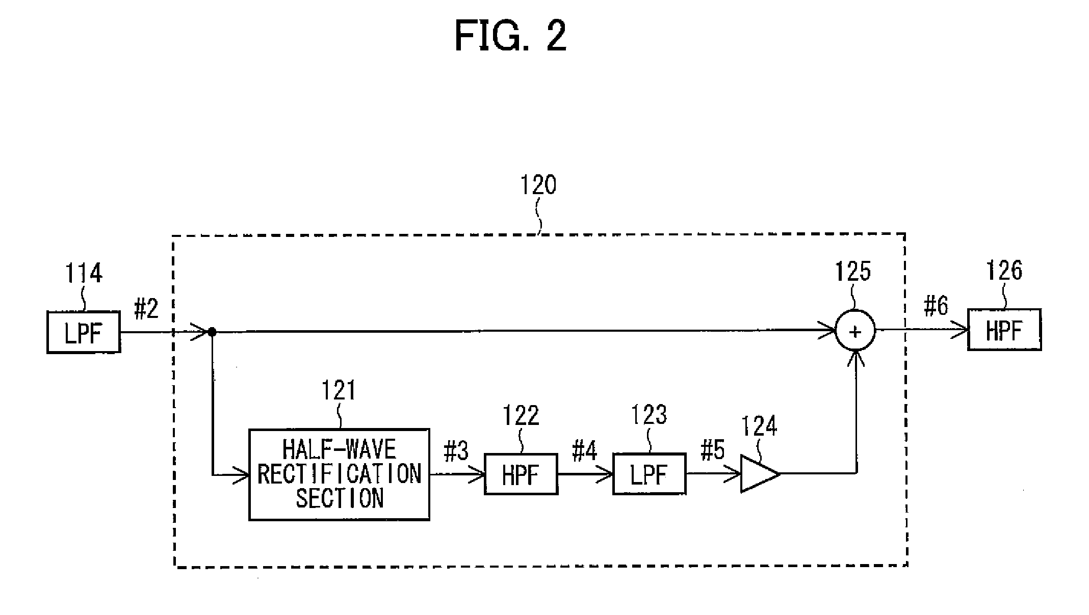
[0083]With reference to FIG. 3 to FIG. 8, the following explains an Example of the harmonics addition carried out by the harmonics addition section 120 of FIG. 2.

[0084]In the present Example, the half-wave rectification 121 carries out half-wave rectification with respect to the low frequency signal #2 so as to add the harmonics containing the fundamental wave to the low frequency signal #2. Further, the cutoff frequency L122 of the high-pass filter 122 is set to 200 Hz, and the cutoff frequency H123 of the low-pass filter 123 is set to 300 Hz, and an amplification factor (or an attenuation factor) of the volume 24 is set to 0 dB.

[0085]FIG. 3 is a graph illustrating frequency characteristics of the high-pass filter 122 and the low-pass filter 123 of the present Example. In this figure, a continuous line indicates a frequency characteristic of the high-pass filter 122 whose cutoff frequency L122 is set to 200 Hz, and a dotted line indicates a freq...

example 2

(Example 2 of the Harmonics Addition)

[0091]With reference to FIG. 9 to FIG. 12, the following explains another Example of the harmonics addition carried out by the harmonics addition section 120 of FIG. 2.

[0092]In the present Example, the half-wave rectification 121 carries out half-wave rectification with respect to the low frequency signal #2 and squares the low frequency signal having been subjected to the half-wave rectification so as to add the harmonics containing the fundamental wave to the low frequency signal #2.

[0093]Also in the present Example, the cutoff frequency L122 of the high-pass filter 122 is set to 200 Hz, and the cutoff frequency H123 of the low-pass filter 123 is set to 300 Hz, and an amplification factor (or an attenuation factor) of the volume 24 is set to 0 dB as in Example 1. Also in the present Example, the low frequency signal #2 whose center frequency is 100 Hz illustrated in FIG. 4(a) and FIG. 4(b) is inputted to the harmonics addition section 120 as in...


PUM


Abstract

A sound signal processing device causes an amplifier to amplify a low frequency signal and synthesizes the amplified low frequency signal with a middle or high frequency signal so as to output the resultant output signal. A gain control section controls a gain of the amplifier on the basis of an amplitude of the output signal. As a result, it is possible to amplify the low frequency signal without any clipping in a receiving end device and without any unstable volume of a middle or high frequency component.

Description

[0001]This Nonprovisional application claims priority under 35 U.S.C. §119(a) on Patent Application No. 204755 / 2007 filed in Japan on Aug. 6, 2007, the entire contents of which are hereby incorporated by reference.FIELD OF THE INVENTION[0002]The present invention relates to a sound signal processing device and a sound signal processing method whereby bass is enhanced. Further, the present invention relates to (a) a sound signal processing program for causing a digital signal processor to function as such a sound signal processing device and (b) a storage medium storing such a sound signal processing program. Also, the present invention relates to a display device having such a sound signal processing device.BACKGROUND OF THE INVENTION[0003]A human audio frequency band ranges from 20 Hz to 20 kHz. In case of reproducing sound with a small speaker, it is impossible to obtain a sufficient sound pressure level corresponding to bass whose frequency is equal to or lower than 100 Hz, so th...

Claims


Application Information

Patent Timeline
Patent Type & Authority Patents(United States)
IPC IPC(8): H03G5/00
CPCH04R3/04H04R2430/03H04R2499/15H04S3/008
Inventor KUBO, KATSUTOSHI
Owner SHARP KK
Why Eureka
Try Eureka